VT591 / Water leak rope sensor (Legacy with WDC)
Function and purpose
Notice on 6th June 2019: The product has been altered. RJ9 4P2C connected is now used instead of 2P Power Terminal.
.png?version=1&modificationDate=1634904645997&cacheVersion=1&api=v2&width=300&height=214)
.png?version=1&modificationDate=1634904645803&cacheVersion=1&api=v2&width=300&height=217)
The sensor must be used together with
| (ordered separately) |
|---|

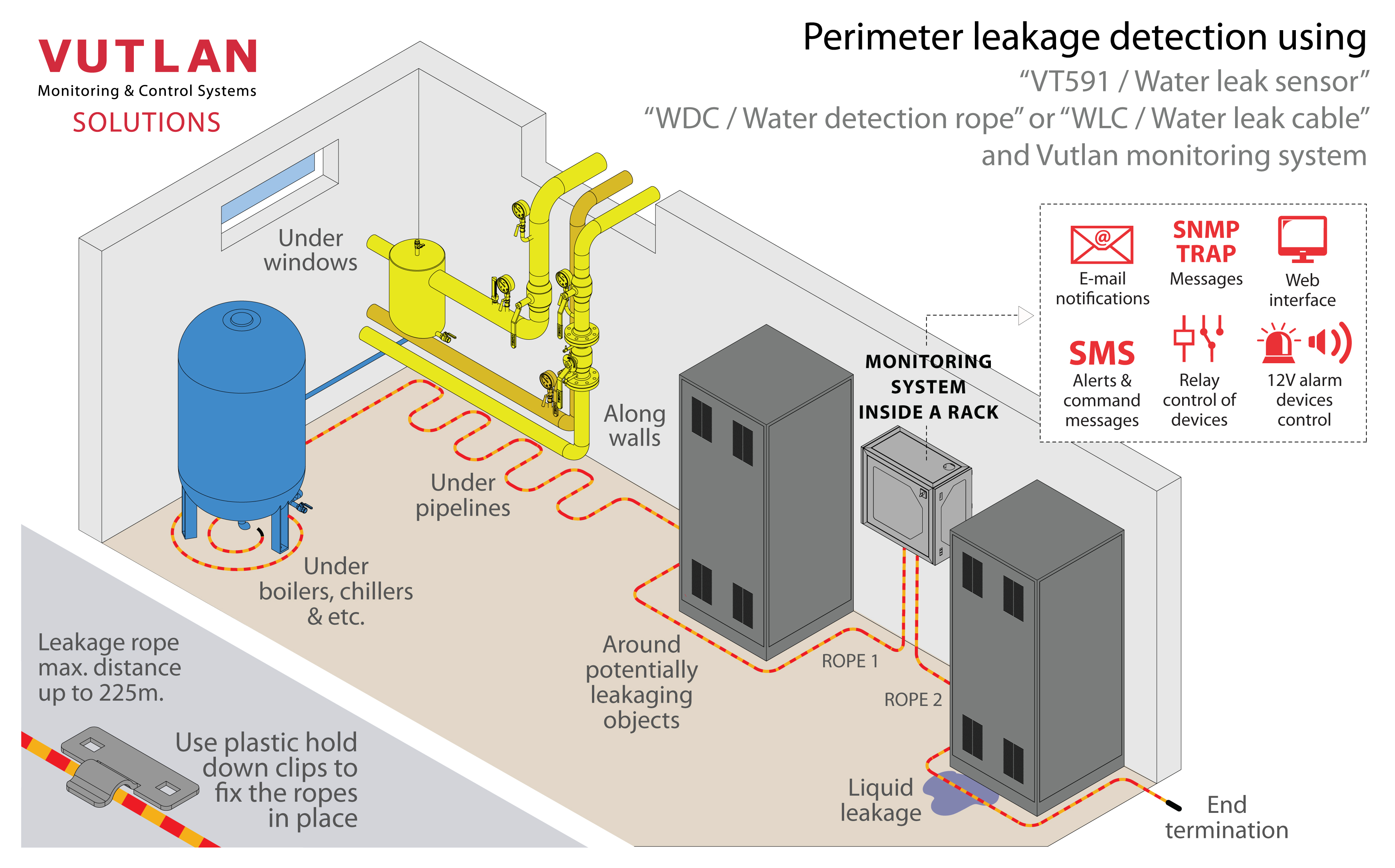
When water is in contact with the detection cable sensor indicates the emergence of moisture. "WDC / Water detection rope" and "WLC / Water leakage cable" are ordered separately! The whole area can be effectively monitored by placing the cable near or along with possible flood sources.
Dimensions
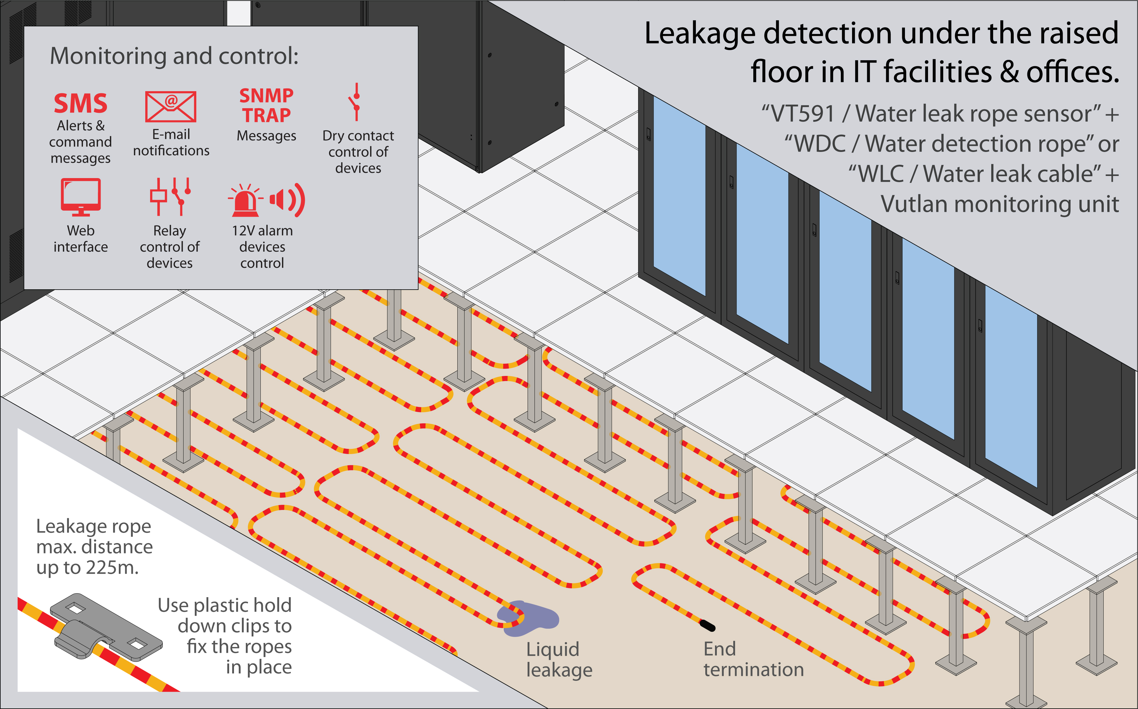
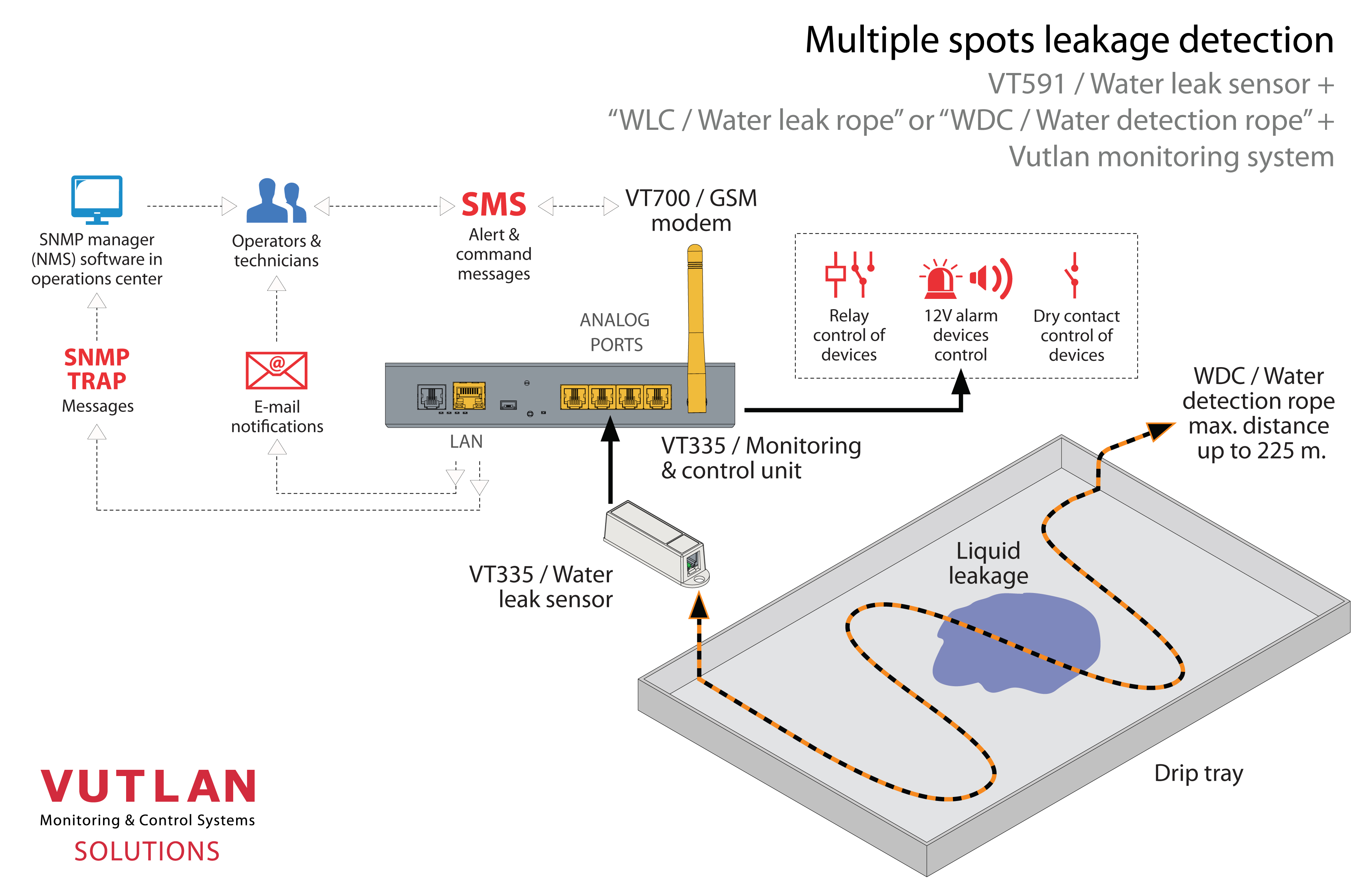
Usage examples
Technical specifications
VT591 / Water leak sensor specifications | |
|---|---|
| Dimensions | 60×18×18 mm |
| Weight | 60 g |
| Input | 2 wire (WDC cable) |
| Output | RJ11 / RJ12 (6p4c) |
| Operating temperature | -10 °C to +80 °C |
| Operating humidity | 5% to 95% (Non-Condensing) |
| Mounting | Mounting bracket included. |
| Power consumption | 60mW |
| Max. distance m | 100 m |
| HS Code | 9025 80 400 |
| Components | Manufactured in E.U. |
| Special features | Response time: 15 sec., Recovery time: Depends on how fast the sensor dries out |
WDC / Water detection rope specifications | |
|---|---|
| Description | WDC can detect moisture (works until the dew point) and does not welcome pollution! |
| Detectable liquids | Clean, polluted & distilled water; acids; alkalis; alcohols, and other electrically conductive liquid |
| Diameter | 3 mm in diameter |
| Lengths | Order options include 6m, 10m, 17m, 25m, 50m, or custom length. |
| Weight | 15 g/m |
| Operating temperature | Min. -50° C, Max. 105° C |
| Max. rope length | 225 m |
| Conductor | 27% Ni |
WLC / Water leak cable specifications | |
|---|---|
| Description | WLC can work in high humidity, pollution, and hazardous waste |
| Detectable liquids | Clean, polluted & distilled water; acids; alkalis; alcohols, and other electrically conductive liquid |
| Diameter | 5.5 mm in diameter |
| Lengths | Order options include 10m, 15m, 25m, 50m, or custom length. |
| Weight | 26 g/m |
| Operating humidity | 0° - 100 % |
| Max. cable length | 225 m |
| Inputs | x2 wires |
Package content
Package includes:
Package content | Description | Quantity | |
|---|---|---|---|
1 | 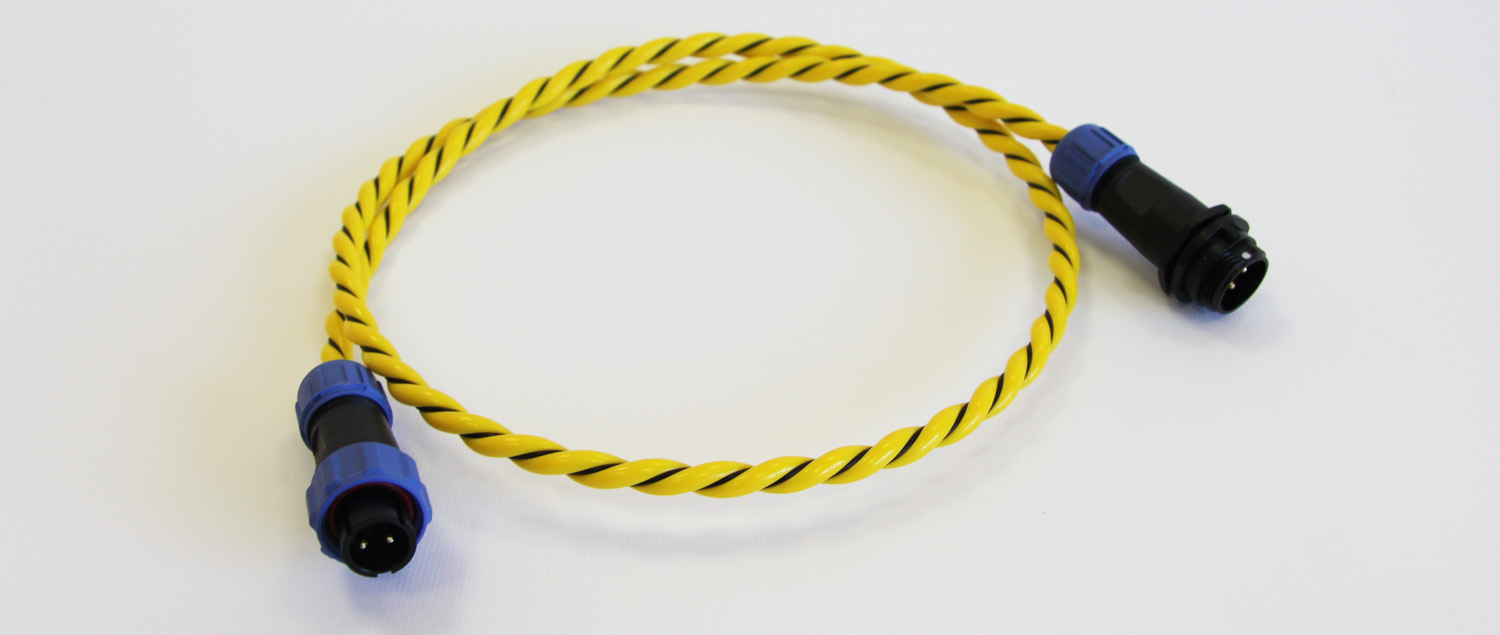 | WLC3/WLC6/WLC10/WLC16/WLC25/WLC50 leakage cable | 1 pc |
2 |  | 4J-S sticky clamps for each 2 m of the rope. | 1 pc |
3 |  | Protective cap | 1 pc |
Connecting WDC / Water detection rope

- Connect the WDC rope sensor to the VT591 leak sensor.
- Wire the WDC rope around or under potentially leaking objects around the perimeter or under raised floors.
- Connect the sensor to the monitoring unit. The connection is plug-an-play.
- The sensor is ready to use.
Connecting WLC / Water leak cable
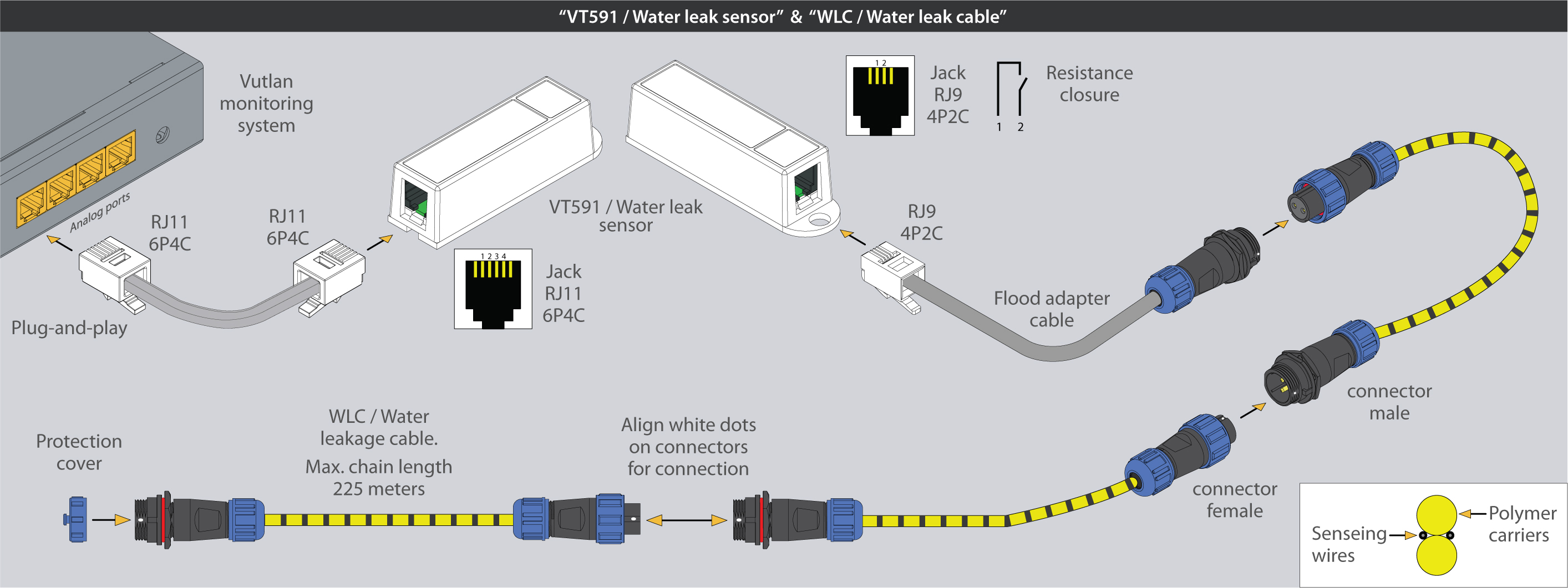
The cable can not touch itself. It needs to be straightened.
Do not twist or press down the cable too much. This may lead to deformation. The cable has two sensing wires, these wires can not touch each other.
Do not put the cable on a conductive surface.
You can cut the cable, but you need to isolate the ends so that they do not touch each other. And do not loop the cable.
- Connect the "VT591 / Water leak sensor" to the monitoring unit. The connection is plug-an-play.
- Connect "VTC / Terminal cable" to the VT591 sensor.
- Connect "WLC / Water detection cable" to "VTC / Terminal cable".
- Connect any additional "WLC / Water detection cables" to each other as shown in the picture above to make a chain connection.
- Wire the WLC rope around or under potentially leaking objects around the perimeter or under raised floors.
- Put a protective cap on the connector of the last WLC cable in a chain.
- The sensor is ready to use.
Analog sensor connection
This section includes child pages:
- VT410 / DC voltage monitor
- VT420 / Converter 4-20mA
- VT500 / Temperature sensor
- VT510 / Humidity sensor
- VT501 / Outdoor temperature sensor
- VT520 / AC voltage monitor
- VT520DIN / AC Voltage monitor (link)
- VT530 / Access sensor
- VT540 / Vibration sensor
- VT550 / Wind velocity meter
- VT560 / Smoke detector
- VT570 / PIR sensor
- VT572 / Radar microwave motion sensor
- VT591 / Leak sensor & WLC / Leak detection cable
- VT593 / Spot leak sensor
- VT594 / BMS leak water sensor
- Chain connection of analog sensors
Connecting analog sensors
Connect the analog sensor by a supplied RJ-11 (6P4C) cable to any analog port "A1 .. A8" or "Sensor" port. The determination of the sensor type and connection will occur automatically.
.jpg?version=1&modificationDate=1707204636707&cacheVersion=1&api=v2&width=760&height=433)
If strong electromagnetic interference is present, we recommend using a 3-pair cable CAN FTP for sensor connection!
6P4C RJ11 cable wiring/pinouts
%20pinouts%20cable.jpg?version=1&modificationDate=1707204779856&cacheVersion=1&api=v2&width=760&height=431)
1- Yellow, 2- Green, 3- Red, 4 - Black
Colors are true for this telephone cable. Both ends match the colors and pinouts (identical).
Please refer to the RJ connectors comparison table:
Daisy chain connection
Some of the analog sensors can be connected to a daisy chain. Please refer to the article "Chain Connection of analog sensors".
Maximum cable length test
ok = tested
x = failed
Model | 50m | 100m | 120m | 150m | 200m | |
|---|---|---|---|---|---|---|
VT407 | AC current converter | ok recommended | ok | |||
VT410 | DC voltage monitor | ok | ||||
VT420 | Converter 4-20mA | ok recommended | ok | |||
VT500 | Temperature sensor | ok | ok | |||
VT501 | Outdoor temperature sensor | ok | ok | |||
VT510 | Humidity sensor | ok | x | |||
VT530 | Access sensor | ok | ||||
VT540 | Vibration sensor | ok | ||||
VT550 | Wind velocity meter | ok | x | |||
VT560 | Smoke detector | ok | ||||
VT570 | PIR sensor | ok | ||||
VT590 | Spot water detector | ok | ||||
VT591 | Water leak sensor | ok |
Extending the number of analog sensors
Using CAN extension "VT408 / Sensor extension unit" it is possible to increase the number of analog sensors connected to the monitoring unit up to 80 sensors.
.jpg?version=2&modificationDate=1707204813374&cacheVersion=1&api=v2&width=723&height=579)
Additional articles of interest
Installation examples
Please find installation examples in our article "Water leakage detection using cable sensor and spot sensor".
Cable pinouts
The sensor uses a standard Vutlan analog sensor cable(RJ11/RJ12 to RJ11/RJ12) for connecting to the monitoring unit. You can find further instructions at: Analog sensors connection
Technical support
The device does not contain any user-serviceable parts. If the power meter requires service, contact your local sales representative. Do not open the device. Opening the device voids the warranty.
Troubleshooting
The following table describes potential problems and their possible causes. It also describes checks you can perform or possible solutions for each. After referring to this table, if you cannot resolve the problem, contact your local Vutlan sales representative for assistance.
| Potential Problem | Possible Cause | Possible Solution |
|---|---|---|
| The data being displayed is inaccurate or not what you expect. | Incorrect setup values. | Check that You use the correct f(x) formula |
| Incorrect voltage inputs. | Check power meter voltage input terminals to verify that adequate voltage is present | |
| The power meter is wired improperly. | Check that all wires are connected correctly and that they are energized. See “Wiring Diagrams” of the device. | |
| The sensor does not appear in the Vutlan monitoring interface | Communication lines are improperly connected. | Check 6P4C RJ11 communication cable. |
| The communication cable is inserted into the wrong port. | 6P4C RJ11 communication cable must be inserted into the analog port of the Vutlan monitoring system. |
Copyright:
Vutlan s.r.o. (LLC)
Remote Infrastructure Monitoring and Control
43 ul.Svornosti, 821 06 Bratislava,
Slovak Republic