Connecting hard disk drive
- Vladimir Tayzhev
- Admin1
Introduction
The 2.5" HDD can be used for AV camera recording.
Installation of Hard disk drive
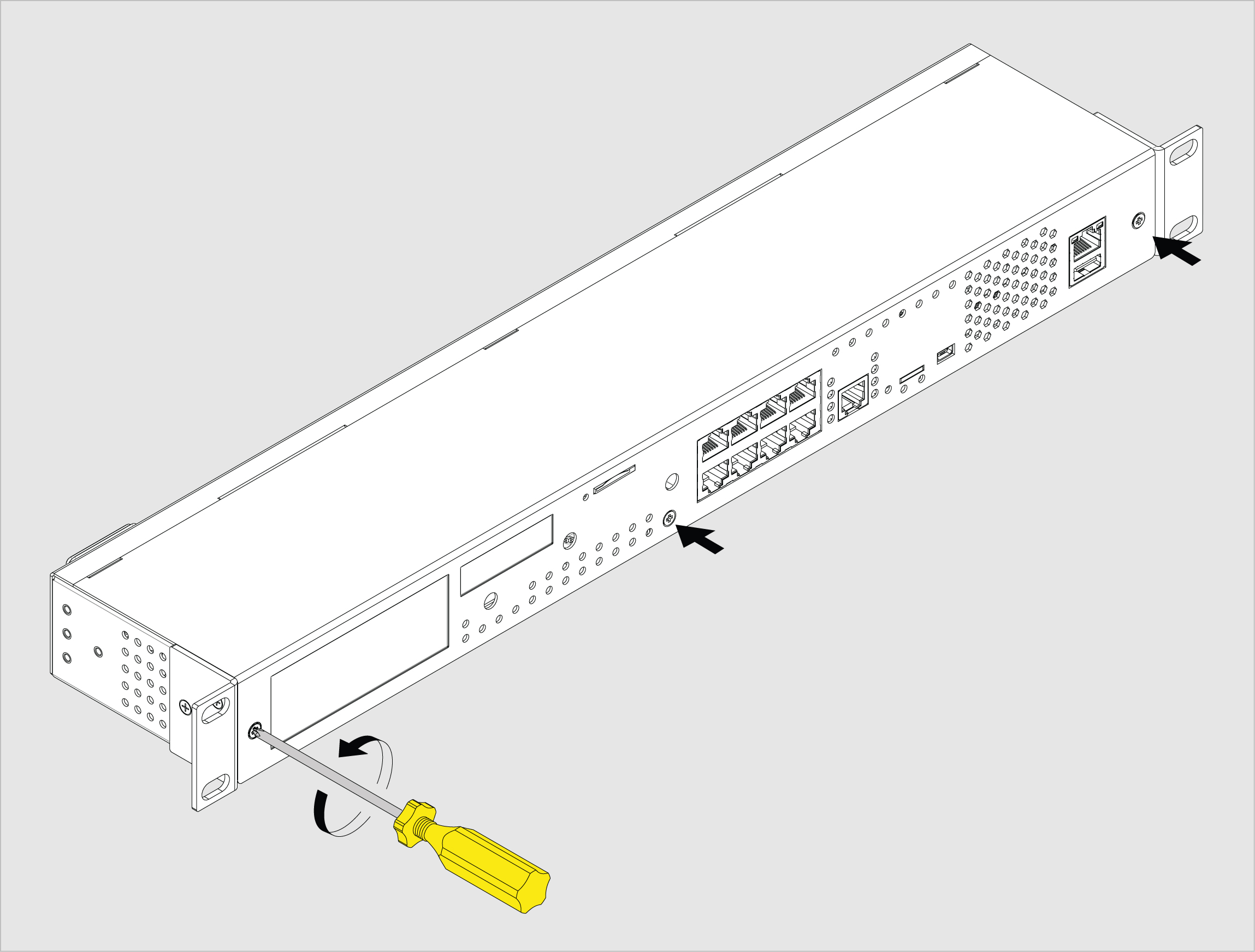
To install connect extensions for the monitoring unit: switch off the appliance, unplug from the outlet or disconnect the power connector.
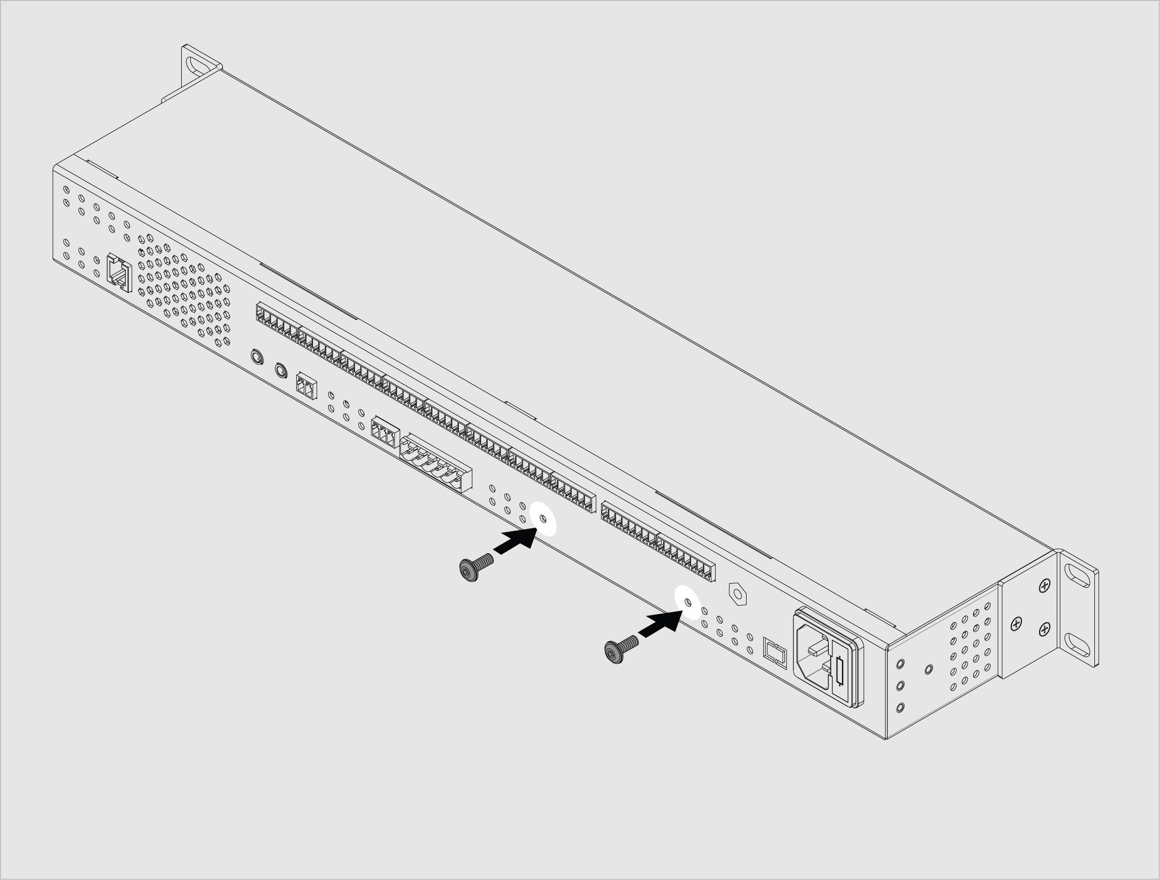
| 1 | Carefully unscrew the screws holding the cover and open it. Depending on the monitoring system, it may have Antenna, LTE modem, Dry Contact boards, or any other additional modules installed inside. Carefully open the box by unplugging, if necessary, any cables that connect from the top cover to the bottom cover. | |
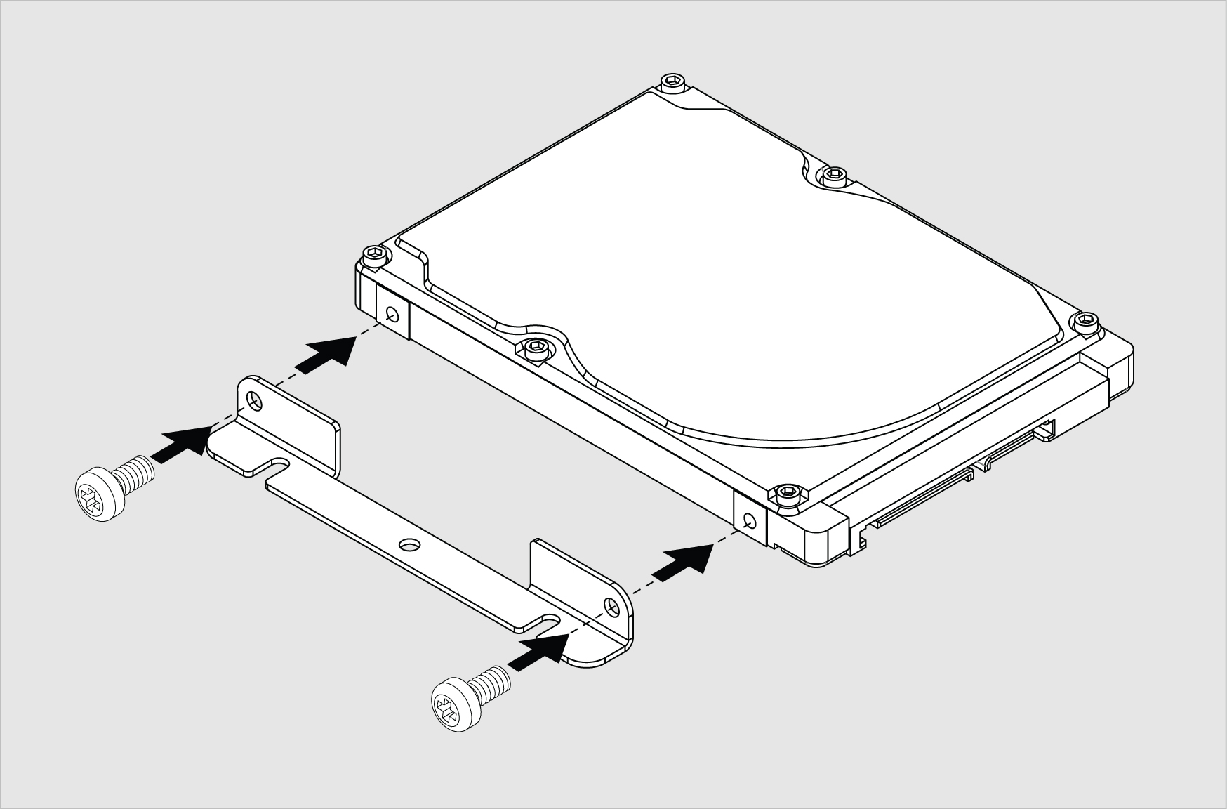
| 2 | Screw the mounting bracket to the 2.5" Hard drive. The mounting bracket is mounted inside the monitoring unit or sold separately together with the HDD. Use M3 screws. | |
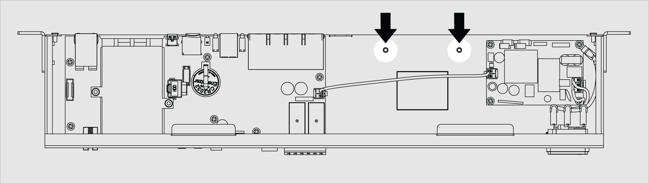
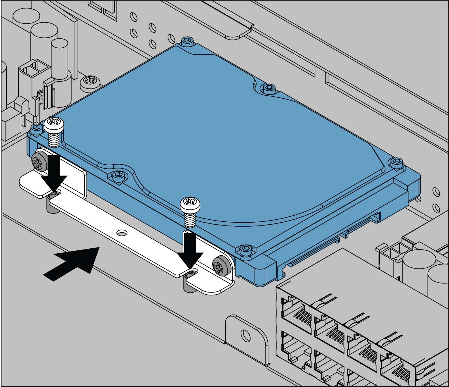
| 3 | Screw together the mounting bracket with the hard drive to the enclosure legs. These two legs can be found using the picture to the left. Use M3 screws. | |
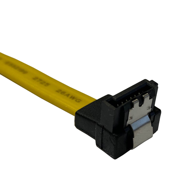
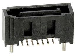
| 4 | SATA ATA data cable 90° clip | Connect the 90° end of the cable to the hard drive disk. The other end of the cable is connected to the MOLEX_67800-5001 connector on the main board of the unit. The cable can be purchased at www.tme.eu . |
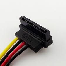
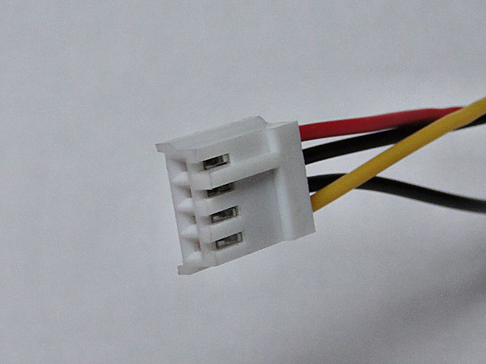
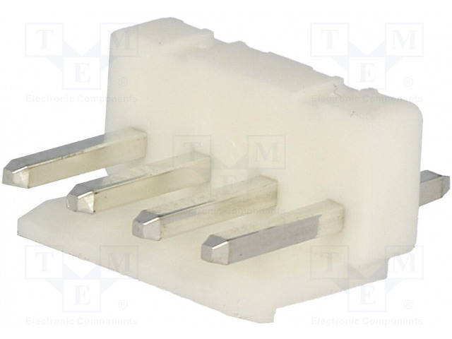
| 5 | SATA power cable: a) For older VT960 systems with a connector 3.96mm pitch.
Left connector: SATA power socket (use only 90 degrees) You can buy part of the connector at https://sk.farnell.com/startech/satapowadapr/lead-molex-right-angle-sata-power/dp/3402760?st=sata%20cable Right connector: Raster signal connector; female; 3.96mm; PIN: 4; NINIGI NS39-G4. You can purchase it from https://www.tme.eu/sk/details/ns39-g4/signalove-konektory-raster-3-96mm/ninigi/. b) For newer VT960 systems with a connector 2.5mm pitch.
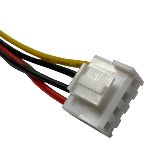
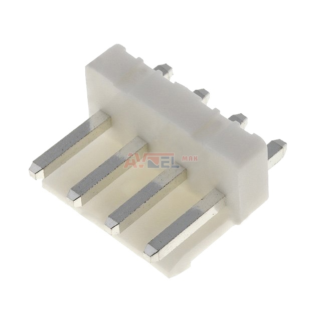
Left connector: SATA power socket You can buy part of the connector at https://sk.farnell.com/startech/satapowadapr/lead-molex-right-angle-sata-power/dp/3402760?st=sata%20cable Right connector: 171822-4, Connector Housing, AMP EI, Socket, 4 Ways, 2.5 mm, AMP EI Series Contacts You can purchase 171822-4 connectors at https://sk.farnell.com/amp-te-connectivity/171822-4/socket-housing-4way/dp/150665 | 1. Connect the SATA power socket end of the cable to the hard drive disk. 2a. For older VT960 systems (3.96mm pitch). Connect the other NS39-G4 end of the cable to the NS39-W4PSocket (3.96mm; PIN: 4) on the mainboard.
2b. For newer VT960 systems (2.5mm pitch):
|
| 6 | Use M3x10mm screws to screw the hard drive to the back wall of the enclosure. |

Configuring HDD settings
Other pages of interest include:
Units of the 900 series have the ability to connect an internal SATA Hard Disk Drive for saving logs, video, etc. To use the recording from an AV camera, an HDD is required.
The HDD must be formatted by the user before installation. The preferred file system is Ext4, a third-party utility (for example, MiniTool Partition Wizard) that can be used for formatting in Windows. The FAT32 file system is also supported, but the storage capacity will be limited to 32 GB.
On the front panel of the unit, there is an LED showing the recording status of the HDD.
To manage the HDD go to the tab: Preferences >> Logging >> HDD.
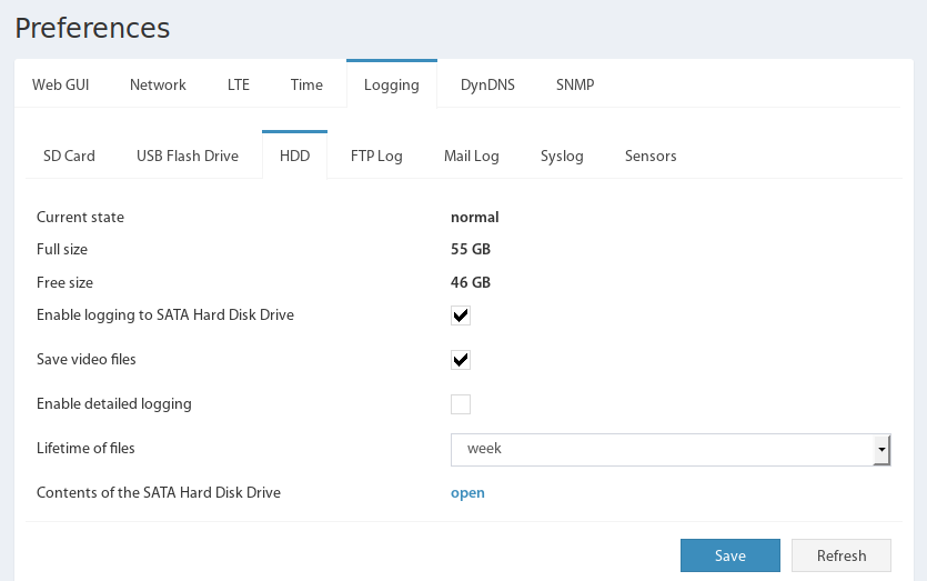
Through this tab, the user can set the logging parameters, and view and manage the status of the HDD:
Current state - reflects the current status of the HDD (normal/ejected/not connected);
Full size - the full memory HDD in gigabytes;
Free size - the free memory HDD in gigabytes;
Enable logging to SATA Hard Disk Drive - enables and disables the logging function on the HDD;
Save video files - enables and disables the function of saving video records;
Enable detailed logging - enables and disables the function of recording per-second values of the selected sensors on the HDD;
Lifetime of files - the lifetime of the files, all older files are deleted from the HDD memory;
Contents of the SATA Hard Disk Drive - specifies a link to the contents of the HDD.
The buttons at the bottom of the panel provide:
Refresh - is used to update the page;
Save - preservation and application of logging parameters.
The files are written to a directory with the name formed from the name of the device type (for example, VT325) and the value of the Network→Hostname field, and has the form VT325-DeviceName. If the name is not specified by the user (by default, hostname), then the IP address of the device is used to form the directory name, and the name has the form VT325-192.168.0.193. Inside this directory, create a directory for the log files (log), video files (video), sensors dump files (sensors), and log archive files (archive). The files are named based on their creation time, and 2016.11.17_16-37-43.log. At the beginning of the log file, upon creation, service information like the device type, software version, IP address, etc is stored. Log files are written in text form. Sensors dump files are recorded in a text table format CSV. The CSV format is supported by many office and engineering programs, including Microsoft Excel, OpenOffice, LabVIEW, etc.
Log files are recorded during the day and are closed at 00:00 by device time. If the device reboots, then new files are created.
The log file is filled in as events occur, and looks like this:
|
Sensor dump files
Read more about Sensors dump files.
Configuring AV camera
Content
Other pages of interest
Introduction
Units of the 900 series have the ability to connect an analog AV camera starting with firmware version 3.8.3. To be able to record video from an AV camera, you will also need to connect an internal SATA HDD.
The camera is displayed as an element in the system tree and is disabled by default. To start playback of the live image from the camera, connect it to the unit and enable AV cam. The delay in displaying the live video is related to the codec and is 3 seconds.

Now the video from the camera will be displayed on the "Cameras" tab. A separate panel is provided for the AV camera.

To be able to save video, you need to connect a SATA HDD and allow the log and video to be saved on it. This is done in the tab: Preferences → Logging → HDD.

From now, the camera will continuously record on the HDD. To save the video, you need to create a logic scheme and set the desired video duration. The saved video will start in advance until the logical scheme is set to alarm. The moment the sensor is triggered (in this example, the motion sensor) will be in the middle of the video clip. Thus, you can see what happened before the alarm was triggered and what happened after.

The archive of created videos can be viewed on the "Cameras" tab in the AV camera panel. As well as the contents of the HDD: Preferences → Logging → HDD → Contents of the SATA Hard Disk Drive.

Developer notes: