VT520DIN / AC Voltage monitor (link)
Product page: https://vutlan.com/analog-sensors/133-vt520din-ac-voltage-monitor.html
Datasheet page: https://vutlan.atlassian.net/l/cp/XJqBinZs
Description
Function and purpose
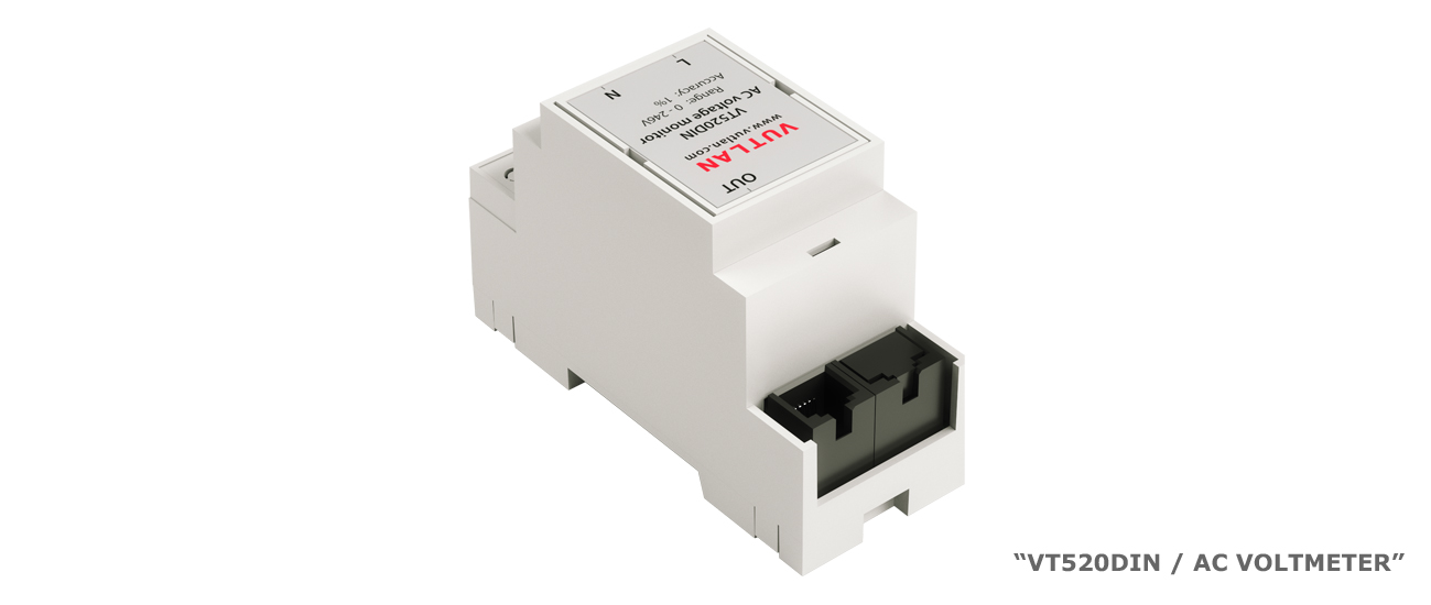
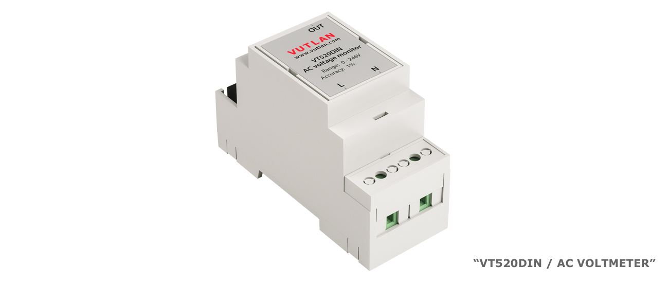
AC voltmeter (a.k.a. sensor, voltage monitor, voltage meter) is needed for the measurement of AC 0-246V. It is an analog plug-and-play sensor. It has a high accuracy of 1%. The device can be monitored using any of Vutlan's monitoring systems, which can be set up to notify and control the equipment in case of an emergency.
Technical specifications
The technical specification can be found on the product page VT520DIN
Components
The sensor consists of
DIN rail 2M plastic housing: flammability rating is UL94V-0; body color is grey; the material is ABS
AC voltage meter board

Package includes:
Package content | Description | Quantity | |
|---|---|---|---|
1 | 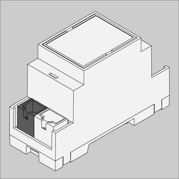 | Voltmeter | 1 pc |
2 | 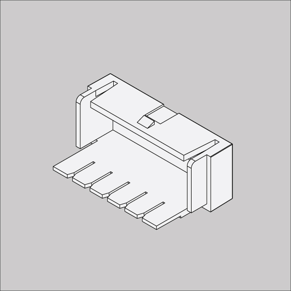 | plastic guard | 1 pc |
3 | 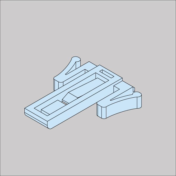 | DIN rail / wall clip | 1 pc |
4 | 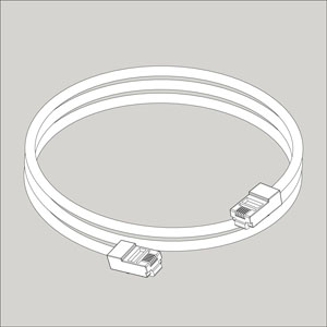 | 6P4C RJ11 Telephone cable 2m | 1 pc |
Safety instructions
Carefully READ and FOLLOW the safety precautions outlined below BEFORE working with the voltmeter.
Only qualified electrical workers should install this equipment. Such work should be performed only after reading this entire set of instructions.
NEVER work alone.
Before performing visual inspections, tests, or maintenance on this equipment, disconnect all sources of electric power. Assume that all circuits are live until they have been completely de-energized, tested, and tagged. Pay particular attention to the design of the power system. Consider all sources of power, including the possibility of backfeeding.
Turn off all power supplying the voltmeter and the equipment in which it is installed before working on it.
Always use a properly rated voltage-sensing device to confirm that all power is off.
Apply appropriate personal protective equipment (PPE) and follow safe electrical work practices. In the USA, see NFPA 70E
Before closing all covers and doors, carefully inspect the work area for tools and objects that may have been left inside the equipment.
Use caution while removing or installing panels so that they do not extend into the energized bus; avoid handling the panels, which could cause personal injury.
The successful operation of this equipment depends upon proper handling, installation, and operation. Neglecting fundamental installation requirements may lead to personal injury as well as damage to electrical equipment or other property.
The power meter should be installed in a suitable electrical and fire enclosure.
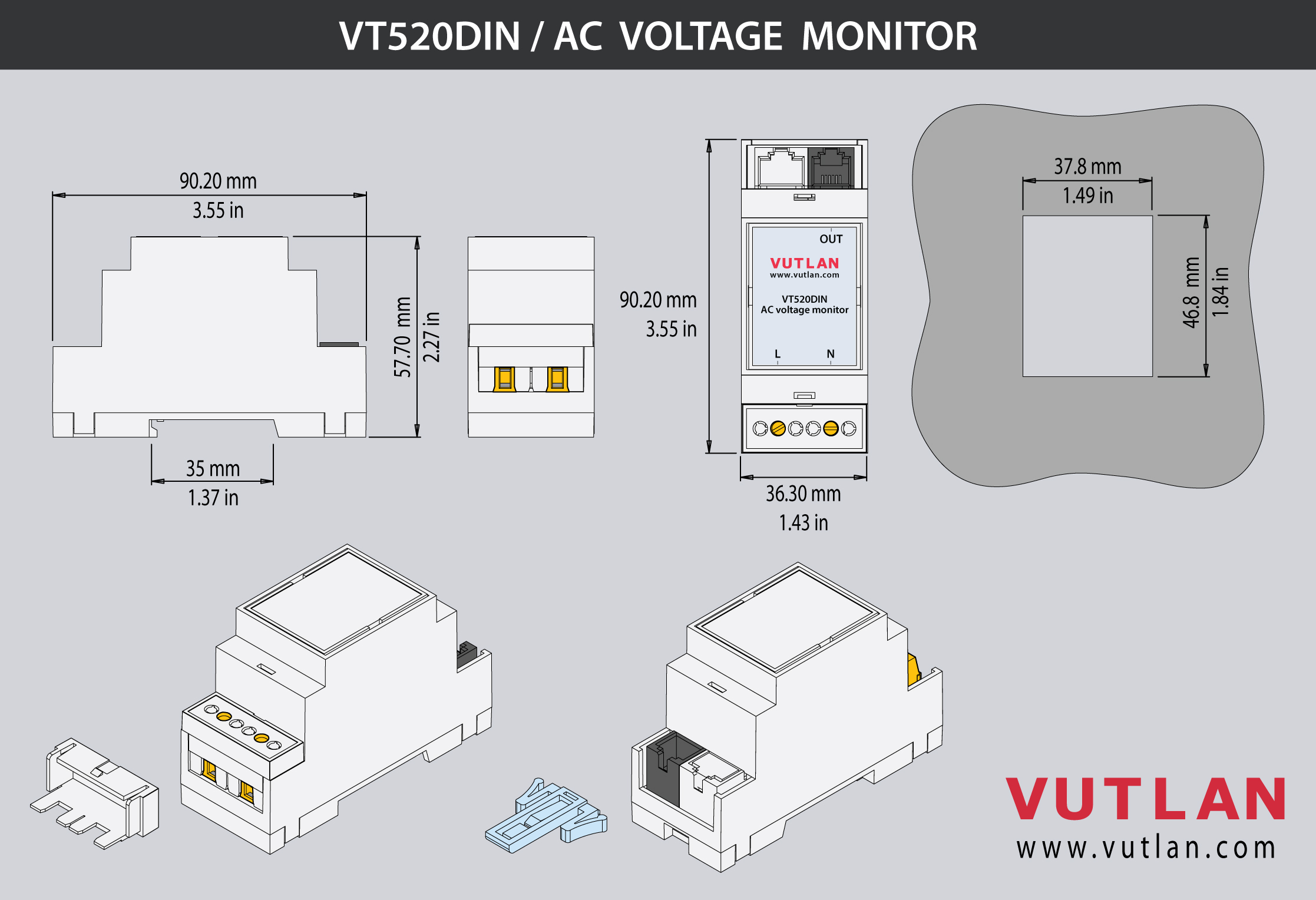
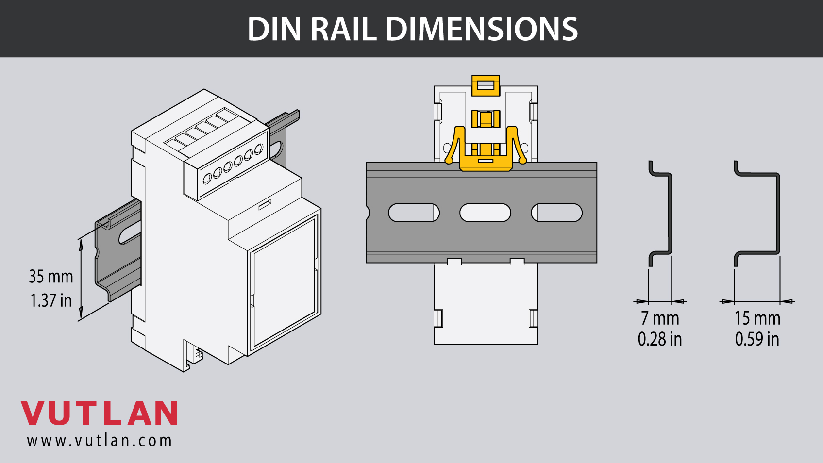
Dimensions
Mounting
1. The device is mounted onto a DIN rail 35mm bar.
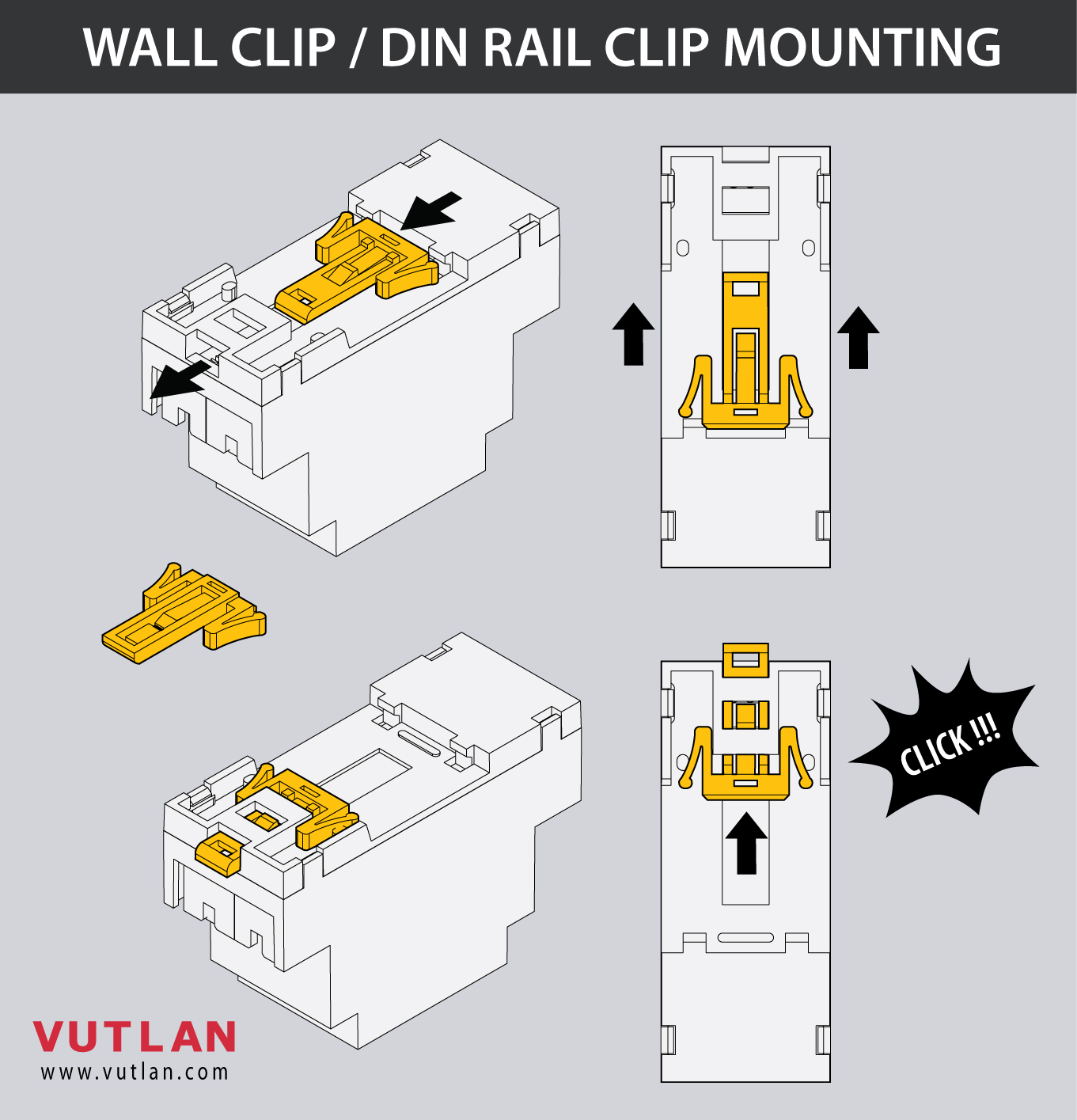
2. Insert the wall clip / DIN rail clip into the enclosure.
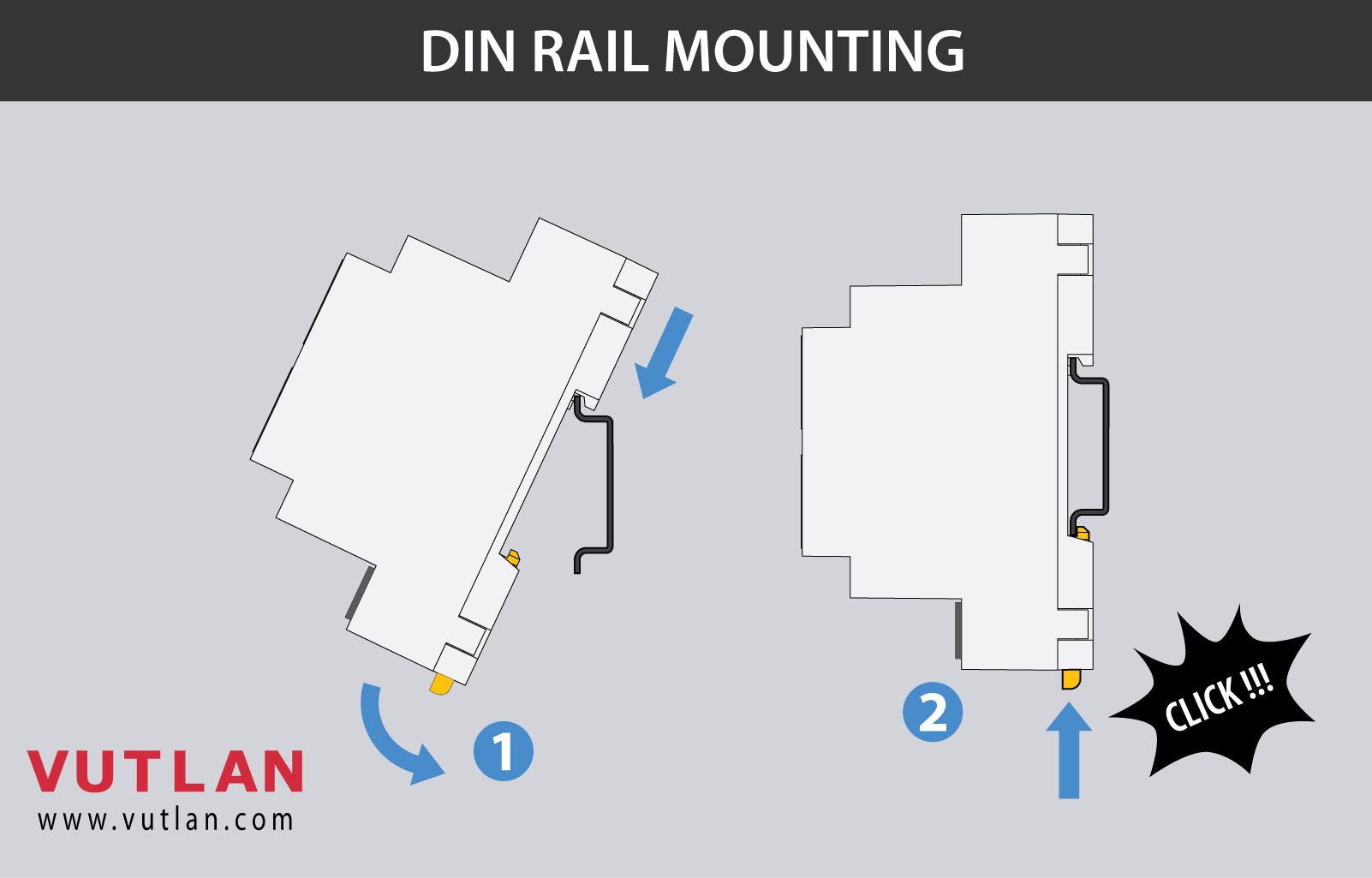
3. Insert/press the enclosure onto the DIN rail bar.
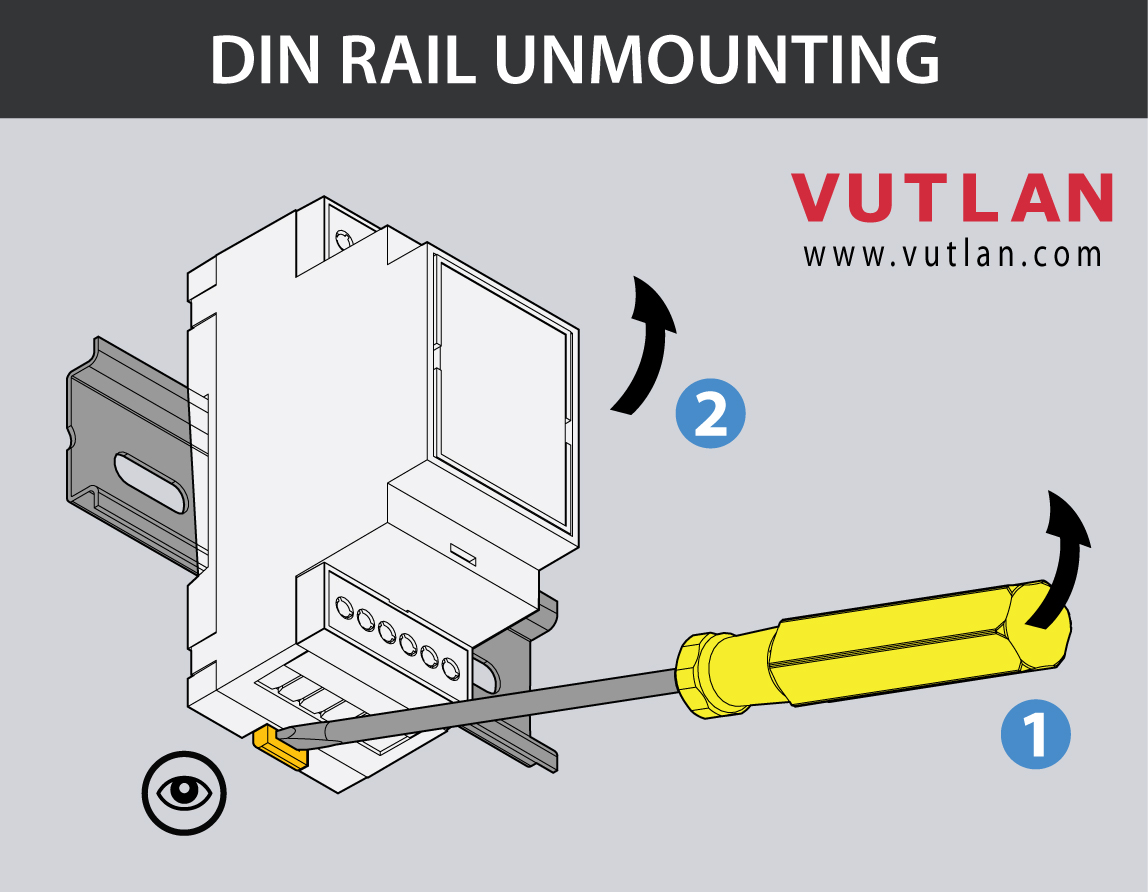
4. In case You need to unmount it, pull the wall clip / DIN rail guard with the screwdriver and pull the enclosure outwards.
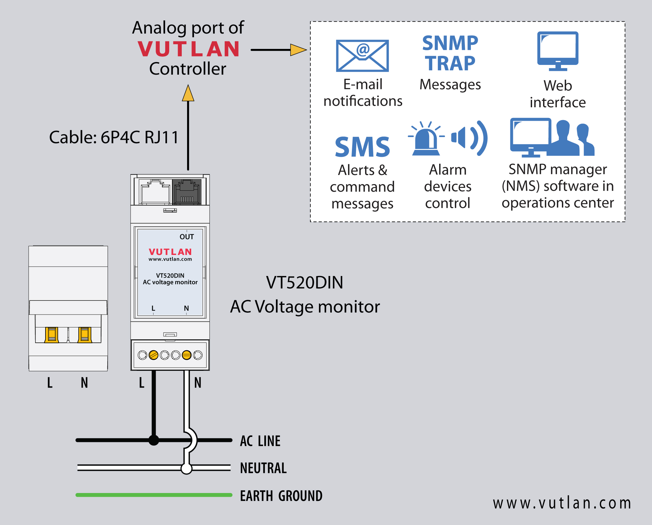
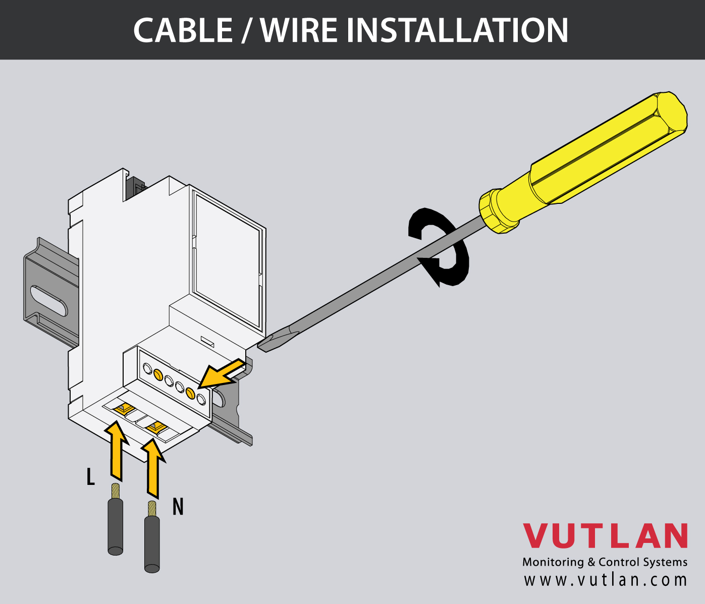
Wiring
1. Switch OFF the power of the AC line and follow other instructions from the section "Safety instructions".
5. Follow power cable specifications for the next step.
Specifications | Strip length | Wire cross-section | Screw head | |
|---|---|---|---|---|
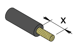 | 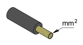 |  | ||
Terminal block Pins: 2P Step: 5.08 mm, 0.2 in
|  | 6 - 7 mm, 0.23 - 0.27 in | 2.5 mm², 0.09 in² #26 - #12 AWG | Flat 3.5 mm, 0.13 in |
6. Insert the power cables.
Make sure You follow "Safety instructions" at the beginning of the instruction.
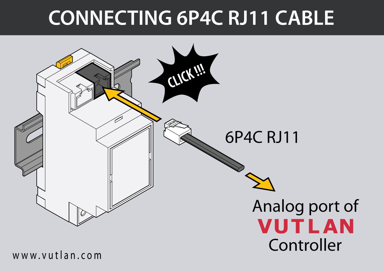
7. Connect the device with the Vutlan monitoring system using a 6P4C RJ11 cable (cable is supplied).
9. Turn the AC line power back ON.
Connecting analog sensors
VT520DIN is an analog plug-and-play sensor. It is connected to an analog port of any Vutlan monitoring system.
This section includes child pages:
- VT410 / DC voltage monitor
- VT420 / Converter 4-20mA
- VT500 / Temperature sensor
- VT501 / Outdoor temperature sensor
- VT510 / Humidity sensor
- VT520 / AC voltage monitor
- VT520DIN / AC Voltage monitor (link)
- VT530 / Access sensor
- VT540 / Vibration sensor v2
- VT550 / Wind velocity meter
- VT560 / Smoke detector
- VT570 / PIR sensor
- VT572 / Radar microwave motion sensor
- VT591 / Leak sensor & WLC / Leak detection cable
- VT593 / Spot leak sensor
- VT594 / BMS leak water sensor
- VT595 / Leak sensor & WLC / Leak detection cable
Connecting analog sensors
Connect the analog sensor by a supplied RJ-11 (6P4C) cable to any analog port "A1 .. A8" or "Sensor" port. The determination of the sensor type and connection will occur automatically.
.jpg?version=3&modificationDate=1717586678055&cacheVersion=1&api=v2&width=760&height=433)
If strong electromagnetic interference is present, we recommend using a 3-pair cable CAN FTP for sensor connection!
6P4C RJ11 cable wiring/pinouts

1- Orange, 2- White Blue, 3- Blue, 4 - White Orange
Colors are true for this telephone cable. Both ends match the colors and pinouts (identical).
Please refer to the RJ connectors comparison table:
Daisy chain connection
Some of the analog sensors can be connected to a daisy chain. Please refer to the article "Chain Connection of analog sensors".
Maximum cable length test
ok = tested
x = failed
Model | 50m | 100m | 120m | 150m | 200m | |
|---|---|---|---|---|---|---|
VT407 | AC current converter | ok recommended | ok | |||
VT410 | DC voltage monitor | ok | ||||
VT420 | Converter 4-20mA | ok recommended | ok | |||
VT500 | Temperature sensor | ok | ok | |||
VT501 | Outdoor temperature sensor | ok | ok | |||
VT510 | Humidity sensor | ok | x | |||
VT530 | Access sensor | ok | ||||
VT540 | Vibration sensor | ok | ||||
VT550 | Wind velocity meter | ok | x | |||
VT560 | Smoke detector | ok | ||||
VT570 | PIR sensor | ok | ||||
VT590 | Spot water detector | ok | ||||
VT591 | Water leak sensor | ok |
Extending the number of analog sensors
Using CAN extension "VT408 / Sensor extension unit" it is possible to increase the number of analog sensors connected to the monitoring unit up to 80 sensors.
.jpg?version=2&modificationDate=1707204813374&cacheVersion=1&api=v2&width=723&height=579)
Chain connection of analog sensors
This procedure applies to the following sensors, which are supported by the appliance and are connected to the analog ports:
Analog sensors | Daisy chain |
|---|---|
□ | |
□ | |
□ | |
□ | |
□ | |
■ | |
□ | |
□ | |
■ | |
□ | |
□ | |
□ | |
□ |
VT530 and VT560 are the only analog sensors that allow non-addressable chain connection. All the sensors in one chain are seen by the system as one sensor. One chain can have up to 10 sensors. Example of such connection:
.jpg?version=3&modificationDate=1717586678055&cacheVersion=1&api=v2&width=749&height=427)
Additional articles of interest
Connection wiring/cable pinouts
Cable 6P4C RJ11
Used for connecting the device with
The transducer and the transceiver are installed together.
Mount the transducer using M4 screws and M4 nuts. The distance between mounting holes is 50 mm.
Mount the current transceiver using M4 screws and M4 nuts. The distance between mounting holes is 60 mm.
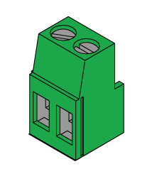
Use a 4-core flat cable and two green connectors supplied with the transceiver and the transducer to assemble the connecting cable.
Configuring analog sensors
Settings tab
To configure a sensor, go to "Main menu" >> "System tree" and click on the sensor element in the tree. A modal window with sensor properties will pop up. Change the needed settings and click "OK" or "Apply" at the bottom of the "Properties" window.
All sensors include:
1 | Name | The name is given by the system automatically. You can change it to anything you want. |
3 | ID | System ID of the element. |
4 | Type | Examples: temperature, humidity, vibration. |
5 | Class | Examples: analog, CAN, switch, discrete. |
6 | Hardware port | The external port number on the device panel to which the sensor is connected (if the sensor is external). |
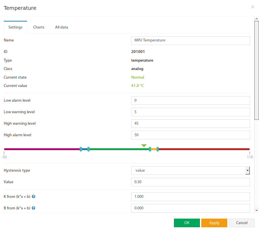
All sensors have threshold controls:
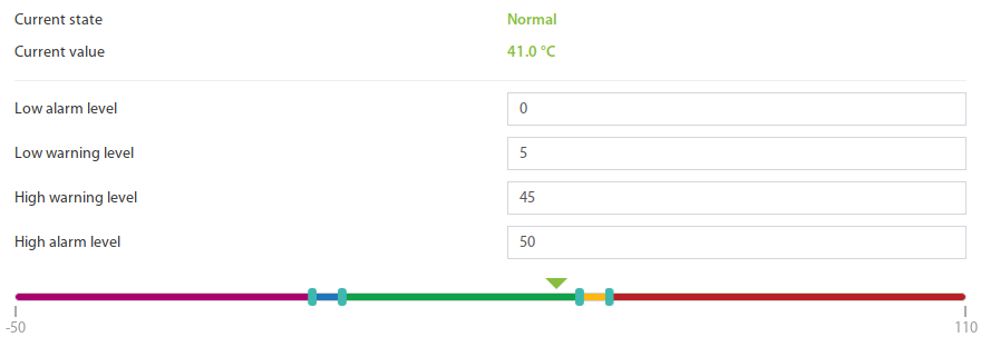
In the picture above, the "Current value" equals 41.0 and is represented by the small triangle. Currently, the triangle is green because it is situated in the "Normal" range. Hence the sensor says that the "Current state" is "Normal". This value is used by the system's "Logic schemes" menu to notify the administrator or take action.
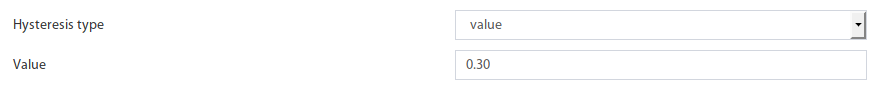
Hysteresis
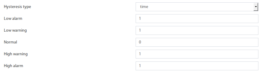
Sensors have the option of setting the hysteresis state. Hysteresis can be a time, a value or it can be disabled.
If the hysteresis is set in time, the sensor will transmit to a new state with a delay of the specified number of seconds in the corresponding field. The time counting will begin from the moment when the measured value of the sensor has left the current range.
Each state has its own field. Which determines the time that the sensor value must continuously hold for the state to change to the specified.
If you set the hysteresis by value, the sensor transition to a new state will occur when the measured value of the sensor exits beyond the current range, adjusted for the specified hysteresis value.
You can calibrate the sensors. Use K and B coefficients. After the calibration, please, save the values in flash memory.
To save sensor properties in the device's flash memory press "  " then "OK" to confirm.
Example: Why do we need to use Hysteresis
Let’s say that we have a temperature sensor. Let’s say that we have set up threshold values.
We have set the value 25.5 °C to be a threshold value between Normal/Alarm states.
If the temperature drops just below 25.5 °C You will have a “Normal” state.
If the temperature goes just above 25.5 °C You will have a “Warning” state.
Sometimes the temperature may stay at 25.5 °C and jump up and down by 0.1-0.3 °C. In this case, You will get too many notifications that the sensor is showing a Warning or Normal state.
In this case, we need to use a Hysteresis.
If the type “time” is chosen, the system will wait for a specified time before the State of the sensor is declared.
If type “value” is used, unless the temperature drops by a larger amount than specified, the sensor state will not be declared.
Tuning the sensor value
Sensor readings can be tunned by a linear formula "y = k * x - b"
Example VT407 + HAT-100Q1 / AC current converter:
Metered current for HAT: from 0 to 100A (This means that the range equals 100, k = 100)
The output of VT407 is 0-5V (That means that the range is equal to 5)
"b" = the value that the sensor shows in WebUI when there's no current. Let's say that b = + 0.021
You should use the following formula for HAT: 100/5*(x-y)
The expression formula would be 20*(x-0.021)
Point is used as a decimal separator (3.14)
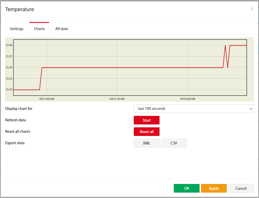
Charts tab
The charts tab shows the following:
Display chart for |
| |
Refresh data | Start | Poll a sensor |
Reset all charts | Reset all | Clears all saved data for the sensor. |
Export data | XML or CSV | Exporting data through WebUI does not work for more than a couple of days and is very rough. If you need detailed log data, use the logging of sensor values to the media. Note: Make sure no endpoint security services used in the network are not blocking the download of XML and CSV files. |
Reset smoke sensors
If analog sensors like VT560 / Smoke detector/ sensor detects smoke or fire, it will go into Alarm mode. Alarm mode can only be switched off manually using the Reset smoke detectors panel or using the onboard sensor Analog sensor power reset is found in the System tree >> Onboard.
Technical support
The device does not contain any user-serviceable parts. If the power meter requires service, contact your local sales representative. Do not open the device. Opening the device voids the warranty.
Troubleshooting
The following table describes potential problems and their possible causes. It also describes checks you can perform or possible solutions for each. After referring to this table, if you cannot resolve the problem, contact your local Vutlan sales representative for assistance.
Potential Problem | Possible Cause | Possible Solution |
|---|---|---|
The data being displayed is inaccurate or not what you expect. | Incorrect setup values. | Check that You use the correct f(x) formula |
Incorrect voltage inputs. | Check power meter voltage input terminals to verify that adequate voltage is present | |
The power meter is wired improperly. | Check that all wires are connected correctly and that they are energized. See “Wiring Diagrams” of the device. | |
The sensor does not appear in the Vutlan monitoring interface | Communications lines are improperly connected. | Check the 6P4C RJ11 communication cable. |
The communication cable is inserted into the wrong port. | 6P4C RJ11 communication cable must be inserted into the analog port of the Vutlan monitoring system. |
Frequently asked questions
Question | Answer |
|---|---|
What is max A for VT520 and VT520DIN? | There are no ampers through VT520/VT520DIN. It has a 140K resistor on the input. |
... |
Copyright:
Vutlan s.r.o. (LLC)
Remote Infrastructure Monitoring and Control
43 ul.Svornosti, 821 06 Bratislava,
Slovak Republic