Product page: https://vutlan.com/analog-sensors/20-vt560-smoke.html
Datasheet page: https://vutlan.atlassian.net/l/cp/Rebjo6pX

Functional description & components
Function
At installation indoors, inside the rack, etc., the sensor monitors the occurrence of smoke inside the building. It is a daisy chain sensor, max. distance from the monitoring unit is 150 meters.
The maximum amount of sensors and maximum length can be extended using the "VT408 / Sensor extension unit".
Components
The smoke sensor consists of a compact plastic housing with ventilation holes.
The sensor can not be used on its own. It must be used together with Vutlan monitoring systems.
Technical specifications
Feature | Description |
|---|---|
Type | Analog |
Dimensions | Ø100×45 mm |
Sensor weight | 150 g |
Packaging weight | 290 g |
Inputs | x2 ports RJ12 |
Operating temperature | Optimal: -10 °C to +55° C Extended: -10 °C to +80° C |
Operating humidity | 5% to 95% (Non-Condensing) |
Average lifespan | >=10 years |
Storage temperature | -10 °C to +55° C |
Storage humidity | 5% to 95% (Non-Condensing) |
Power consumption | 100 mW |
Status Indicators | Red LED |
Max. distance m | 150 m |
HS Code | 8531 10 950 |
Components | Manufactured in E.U. |
Daisy chain | Yes, sensors can be connected in a chain. The system will show all daisy chain sensors in one chain as one sensor. |
Mounting | On the сeiling |
Drawing


Package content
Package content | Description | Quantity | |
|---|---|---|---|
1 |  | Smoke detector | 1 pc |
2 |  | Telephone cable 2m | 1 pc |
3 |  | Sensor bracket | 1 pc |
4 |  | M3.5x10 mm bolts | 2 pcs |
5 |  | Screws M3.5, length 19mm | 2 pcs |
6 |  | M3.5 nuts | 2 pcs |
7 |  | M3.5 washers | 2 pcs |
Safety instructions
Please observe the valid regulations for installation in the country in which the smoke alarm is installed and operated, and the national regulations for accident prevention. Please also observe any internal company regulations, such as work, operating, and safety regulations.
The technical specifications and limit values stated must not be exceeded under any circumstances. In particular, this applies to the specified ambient temperature range and IP protection category.
If a higher IP protection category is required for a special application, the smoke alarm must be installed in an appropriate housing or an appropriate enclosure with the required IP protection category.
Siting location requirements
To ensure the proper functioning of the unit, the conditions for the installation site of the unit specified in section “Technical specifications” must be observed.
Electromagnetic interference
Interfering electrical installations (high frequency) should be avoided.
Installation procedure
Notes on assembly
It is vital to ensure that the smoke alarm is always assembled with the sensor head pointing downwards. In any other position, there is no guarantee that smoke will be detected.
The smoke alarm must also be positioned so that it is ventilated with an adequate amount of air and the ventilation slots are not covered.
Installation with the mounting plate provided
The smoke alarm is installed using the mounting plate provided.

Uncover the smoke detector head from the base.
Attach the smoke sensor base to the mounting plate using the M4 x 10 screws provided.
Replace the sensor head onto the base and secure it by twisting it until it locks home.
Secure the mounting plate to the enclosure frame using the 4.8 x 19 screws.
Remove the red protective cap!

Connecting the smoke sensor
Connect one end of the RJ11 / RJ12 cable to the monitoring unit and the other end to any of the two inputs of the smoke sensor. It is possible to connect up to 10 sensors to one analog port. To do so connect the new RJ11 cable to a free input of the already connected smoke sensor and the other end to the next smoke sensor in a chain. See the picture below. RJ11 or RJ12 cable pinouts can be found in the picture below. After the system will start and sense the smoke detector, the LED on the smoke detector will blink dimly once a second.

Testing the smoke sensors
During system operation, take a needle or paper clip and insert it into the hole on the cover of the sensor, try to move it there until the blinking dimly LED will flash brightly. That means that sensor is in a good state. After inspection, return the sensor /s to a normal state. To do this, either disconnect them from the system, or in a system interface, go to the smoke sensors tab, and restart them.
Connecting analog sensors
This section includes child pages:
- VT410 / DC voltage monitor
- VT420 / Converter 4-20mA
- VT500 / Temperature sensor
- VT510 / Humidity sensor
- VT501 / Outdoor temperature sensor
- VT520 / AC voltage monitor
- VT520DIN / AC Voltage monitor (link)
- VT530 / Access sensor
- VT540 / Vibration sensor
- VT550 / Wind velocity meter
- VT560 / Smoke detector
- VT570 / PIR sensor
- VT572 / Radar microwave motion sensor
- VT591 / Leak sensor & WLC / Leak detection cable
- VT593 / Spot leak sensor
- VT594 / BMS leak water sensor
- Chain connection of analog sensors
Connecting analog sensors
Connect the analog sensor by a supplied RJ-11 (6P4C) cable to any analog port "A1 .. A8" or "Sensor" port. The determination of the sensor type and connection will occur automatically.
.jpg?version=1&modificationDate=1707204636707&cacheVersion=1&api=v2&width=760&height=433)
If strong electromagnetic interference is present, we recommend using a 3-pair cable CAN FTP for sensor connection!
6P4C RJ11 cable wiring/pinouts
%20pinouts%20cable.jpg?version=1&modificationDate=1707204779856&cacheVersion=1&api=v2&width=760&height=431)
1- Yellow, 2- Green, 3- Red, 4 - Black
Colors are true for this telephone cable. Both ends match the colors and pinouts (identical).
Please refer to the RJ connectors comparison table:
Daisy chain connection
Some of the analog sensors can be connected to a daisy chain. Please refer to the article "Chain Connection of analog sensors".
Maximum cable length test
ok = tested
x = failed
Model | 50m | 100m | 120m | 150m | 200m | |
|---|---|---|---|---|---|---|
VT407 | AC current converter | ok recommended | ok | |||
VT410 | DC voltage monitor | ok | ||||
VT420 | Converter 4-20mA | ok recommended | ok | |||
VT500 | Temperature sensor | ok | ok | |||
VT501 | Outdoor temperature sensor | ok | ok | |||
VT510 | Humidity sensor | ok | x | |||
VT530 | Access sensor | ok | ||||
VT540 | Vibration sensor | ok | ||||
VT550 | Wind velocity meter | ok | x | |||
VT560 | Smoke detector | ok | ||||
VT570 | PIR sensor | ok | ||||
VT590 | Spot water detector | ok | ||||
VT591 | Water leak sensor | ok |
Extending the number of analog sensors
Using CAN extension "VT408 / Sensor extension unit" it is possible to increase the number of analog sensors connected to the monitoring unit up to 80 sensors.
.jpg?version=2&modificationDate=1707204813374&cacheVersion=1&api=v2&width=723&height=579)
Additional articles of interest
Analog sensor configuration
Settings tab
To configure a sensor, go to "Main menu" >> "System tree" and click on the sensor element in the tree. A modal window with sensor properties will pop up. Change the needed settings and click "OK" or "Apply" at the bottom of the "Properties" window.
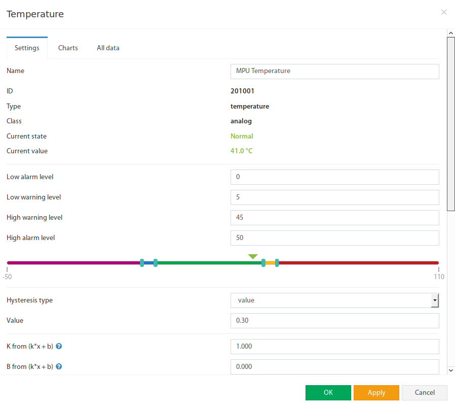
All sensors include:
1 | Name | The name is given by the system automatically. You can change it to anything you want. |
3 | ID | System ID of the element. |
4 | Type | Examples: temperature, humidity, vibration. |
5 | Class | Examples: analog, CAN, switch, discrete. |
6 | Hardware port | The external port number on the device panel to which the sensor is connected (if the sensor is external). |
All sensors have threshold controls:
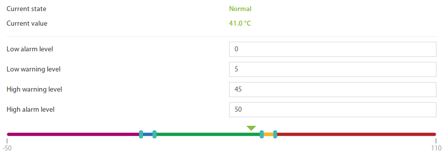
In the picture above, the "Current value" equals 41.0 and is represented by the small triangle. Currently, the triangle is green because it is situated in the "Normal" range. Hence the sensor says that the "Current state" is "Normal". This value is used by the system's "Logic schemes" menu to notify the administrator or take action.
Hysteresis
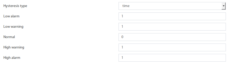
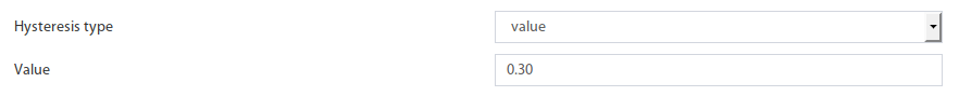
Sensors have the option of setting the hysteresis state. Hysteresis can be a time, a value or it can be disabled.
If the hysteresis is set in time, the sensor will transmit to a new state with a delay of the specified number of seconds in the corresponding field. The time counting will begin from the moment when the measured value of the sensor has left the current range.
Each state has its own field. Which determines the time that the sensor value must continuously hold for the state to change to the specified.
If you set the hysteresis by value, the sensor transition to a new state will occur when the measured value of the sensor exits beyond the current range, adjusted for the specified hysteresis value.
You can calibrate the sensors. Use K and B coefficients. After the calibration, please, save the values in flash memory.
To save sensor properties in the device's flash memory press "  " then "OK" to confirm.
Example: Why do we need to use Hysteresis
Let’s say that we have a temperature sensor. Let’s say that we have set up threshold values.
We have set the value 25.5 °C to be a threshold value between Normal/Alarm states.
If the temperature drops just below 25.5 °C You will have a “Normal” state.
If the temperature goes just above 25.5 °C You will have a “Warning” state.
Sometimes the temperature may stay at 25.5 °C and jump up and down by 0.1-0.3 °C. In this case, You will get too many notifications that the sensor is showing a Warning or Normal state.
In this case, we need to use a Hysteresis.
If the type “time” is chosen, the system will wait for a specified time before the State of the sensor is declared.
If type “value” is used, unless the temperature drops by a larger amount than specified, the sensor state will not be declared.
Tuning the sensor value
Sensor readings can be tunned by a linear formula "y = k * x - b"
Example VT407 + HAT-100Q1 / AC current converter:
Metered current for HAT: from 0 to 100A (This means that the range equals 100, k = 100)
The output of VT407 is 0-5V (That means that the range is equal to 5)
"b" = the value that the sensor shows in WebUI when there's no current. Let's say that b = + 0.021
You should use the following formula for HAT: 100/5*(x-y)
The expression formula would be 20*(x-0.021)
Point is used as a decimal separator (3.14)
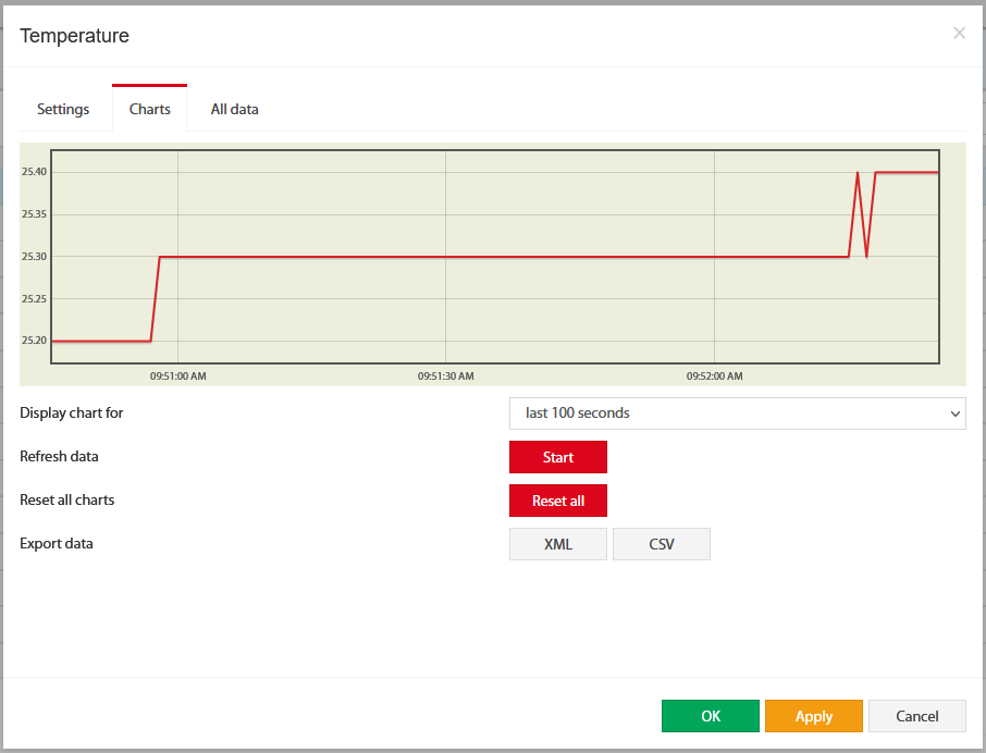
Charts tab
The charts tab shows the following:
Display chart for |
| |
Refresh data | Start | Poll a sensor |
Reset all charts | Reset all | Clears all saved data for the sensor. |
Export data | XML or CSV | Exporting data through WebUI does not work for more than a couple of days and is very rough. If you need detailed log data, use the logging of sensor values to the media. Note: Make sure no endpoint security services used in the network are not blocking the download of XML and CSV files. |
Reset smoke sensors
If analog sensors like VT560 / Smoke detector/ sensor detects smoke or fire, it will go into Alarm mode. Alarm mode can only be switched off manually using the Reset smoke detectors panel or using the onboard sensor Analog sensor power reset is found in the System tree >> Onboard.
Copyright:
Vutlan s.r.o. (LLC)
Remote Infrastructure Monitoring and Control
43 ul.Svornosti, 821 06 Bratislava,
Slovak Republic