VT18 extension board
![]() End of Life
End of Life
Documentation page: https://vutlan.atlassian.net/wiki/spaces/DEN/pages/71181205/Connecting+VT18+extension+board
Website link for "VT18 / Extension board": https://vutlan.com/extension-boards/92-vt18-extension-board.html
Allows addressed correlation of dry contacts and relays responses and permits, adequate measures to be taken/established by the system logic.
Board is mounted and connected inside of VT825 and VT825DC Vutlan monitoring systems. The module adds x8 dry contacts (Inputs), x2 loads (latching relays with LEDs indicators on the front) & a 12V DC power backup terminal.
.jpg?version=1&modificationDate=1610528218726&cacheVersion=1&api=v2&width=449&height=250)
Panels
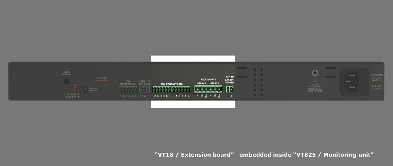
"VT18 / Extension board" mounted on VT825DC monitoring system (back panel):
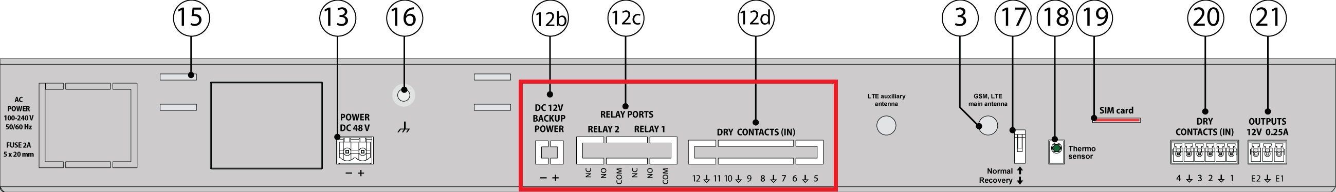
"VT18 / Extension board" mounted on VT825DC monitoring system (back panel):
-03.jpg?version=1&modificationDate=1610528266478&cacheVersion=1&api=v2&width=800&height=115)
"VT18 / Extension board" mounted on VT825DC or VT825 monitoring systems (front panel):
.jpg?version=1&modificationDate=1610528265330&cacheVersion=1&api=v2&width=800&height=152)
Drawing
Inventory
Supply includes
№ | Component | Description |
|---|---|---|
1 | 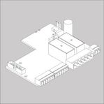 | VT18 / Extension board |
2 | 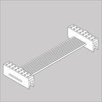 | BH16 to BH16 cable |
3 | 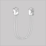 | 2 power cables |
4 | 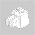 | Terminal plug 2 pins, 3.81 mm - 1 pc |
5 | 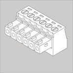 | Terminal plug 6 pins, 3.5 mm - 2 pcs |
6 | 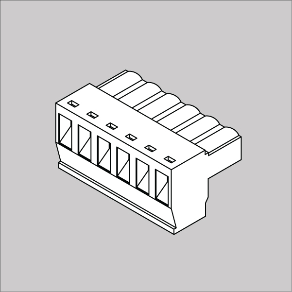 | Terminal plug 6 pins, 5.08 mm - 1 pc |
7 |  | M3*6mm bolts 4 pcs |
Installation of VT18
VT825 (or VT825DC) monitoring unit has the possibility of installing a VT18 expansion board. The board is mounted and connected inside the monitoring unit. The expansion board has 8 dry contact inputs, two bistable 230V / 10A relays, and a power backup input.
To install and connect extension boards: turn off the device, remove the plug from the outlet or disconnect the power terminal.
| 1 | 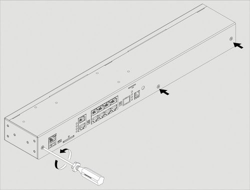 | The VT18 expansion board is installed only in the VT825 or VT825DC monitoring units! Unscrew the 3 bolts on the front of the unit. Antennas, Modem board (VT760 or VT700), "VT10 / 1-Wire board" or "VT85 / Modbus board" can already be installed inside. Carefully open the cover and carefully disconnect the wires of the 1-Wire panel, unscrew the screws and remove it. |
| 2 | 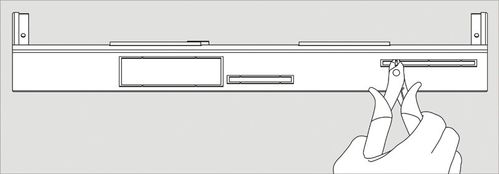 | Open the covers of the expansion panel holes in the device. Bite off the thin bridges in the hole. Check that there are no more left protruding parts. |
| 3 | Install expansion board on 4 support in the bottom of the case, screw the VT18 board to the posts. | |
| 4 | Connect the "IDC16 Flat Cable" to the connector on the expansion board and the connector on the device's motherboard. Switch the power cords from the power supply to the VT16 board and connect the power output from the VT16 to the power input of the VT805 motherboard. | |
| 5 | 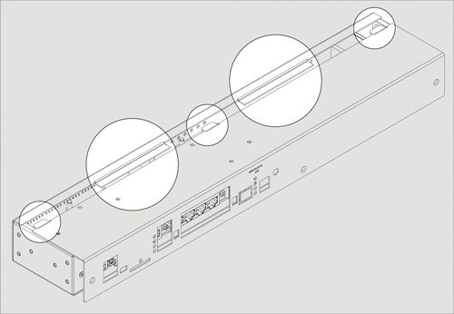 | Check if the cables are connected correctly. Carefully place the top cover of the case so that the wings on the picture do not scratch the case. Make sure that the cable and wires lying inside the device do not interfere with a cover. Make sure that the board terminals crawl through the bottom cover. Do not use force! Close and tighten the cover of the device. |
| 6 | Connect the power plugs to the connectors. |
Connecting relays
Introduction
Applicable for appliances: VT825 & VT825DC with VT18 / extension module, VT825i, VT825ii, VT855i, VT855ii, VT960i, VT960ii,
These systems can connect up to x2 loads managed by built-in relays. Built-in relays have independent separate entrances and exits. The appliances use latching relays, when the power on the appliance switches on/off, relays remain in the command position!
Purpose
Relays are needed for control of AC/DC mains: e.g. lamps, fans, or other devices.
The maximum possible output current of the relay is 10A.
The maximum voltage for DC current is 9-30V.
Function
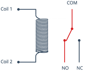
A relay is an electromagnetic switch operated by a relatively small current that can control a much larger current.
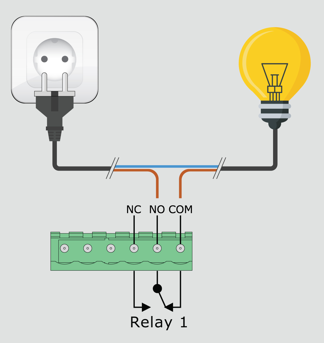
The relay has 5 pins, x3 of them are high voltage terminals (NC, COM, and NO) that connect to the device you want to control.
The mains electricity enters the relay at the common (COM) terminal. While the use of NC & NO terminals depends upon whether you want to turn the device ON or OFF.
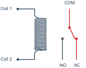
Example 1: When current flows through the coil, the electromagnet becomes charged and moves the internal contacts of the switch. Normally open (NO) terminal connects to the common (COM), and the normally closed (NC) terminal becomes disconnected.
Example 2: When the current stops flowing through the coil, the internal contact returns to its initial state i.e. the normally closed (NC) terminal connects to the common (COM), and the normally open (NO) terminal reopens.
COM (Common): This is the pin you should connect to the signal (mains electricity in our case) you are planning to switch.
NC (Normally Closed): A normally closed configuration is used when you want to turn off the relay by default. In this configuration, the relay is always closed and remains closed until you send a signal from the Vutlan monitoring system to the relay module to open the circuit.
NO (Normally Open): A normally open configuration works the other way in which the relay is always open until you send a signal from the Vutlan monitoring system to the relay module to close the circuit.
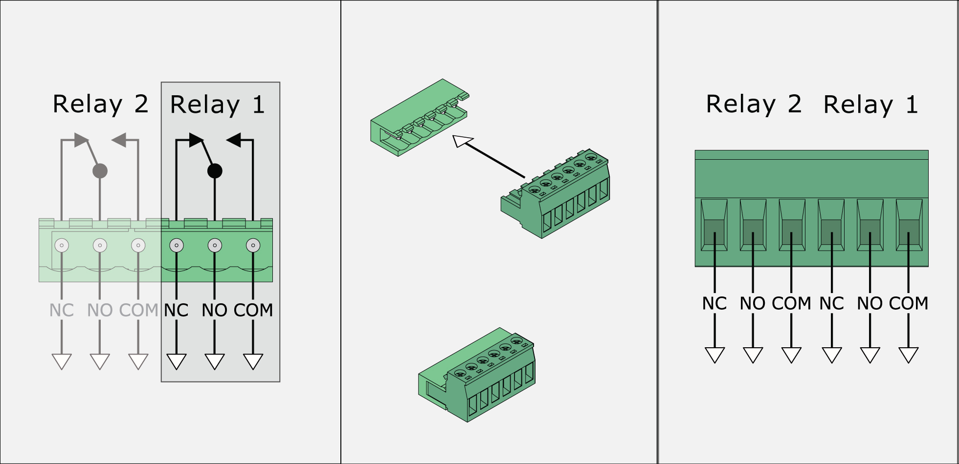
Connecting the load using relays
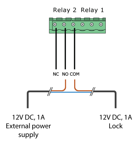
The maximum possible output current of the relay is 10A.
The maximum voltage for DC current is 9-30V.
Do not insert the terminal plug into the relay terminal socket RLY1 ... RLY2 while the external voltage source is turned on.
Example 1: Controlling AC 230V light
Example 2: Controlling DC 12V, 1A lock
Connecting dry contacts
Using dry contacts can connect the door sensor, window sensor, or other contacts to the monitoring units. Dry contacts have two types: Inputs and Outputs.
Keywords: alarm inputs, digital inputs, dry contact inputs, dry inputs, volt-free contacts, UPS monitoring,
Dry Contact Inputs (also known as "Alarm inputs", and "Digital inputs")
The inputs of the dry contact must be connected to the outputs of the relay, Opto-relay, button, or switch. It is not allowed to apply any voltage to the dry contact input.
Only a button/relay/switch is connected to the dry contact inputs.
No signals or input voltage can be applied.
Contacts can be controlled inside the "Dry Contacts / Dry Inputs" panel of the Web Interface of the monitoring unit. The initial state can be configured.
Connection
Connect the wires from the contacts to the corresponding terminals of the connector, each two contacts have a common ground. Plug the terminal into the contact socket. After connecting, configure the trigger logic in the system interface.
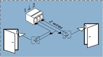
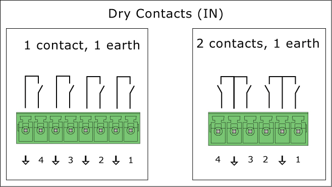
Vutlan monitoring systems may have different types of dry contact inputs:
a) 1 contact and 1 earth
b) 2 contacts and 1 earth
To avoid damage, do not connect the load when the monitoring unit is ON.
Dry contact settings
Link to the included page: Dry contacts settings
Other pages of interest include: "Connecting dry contacts inputs".
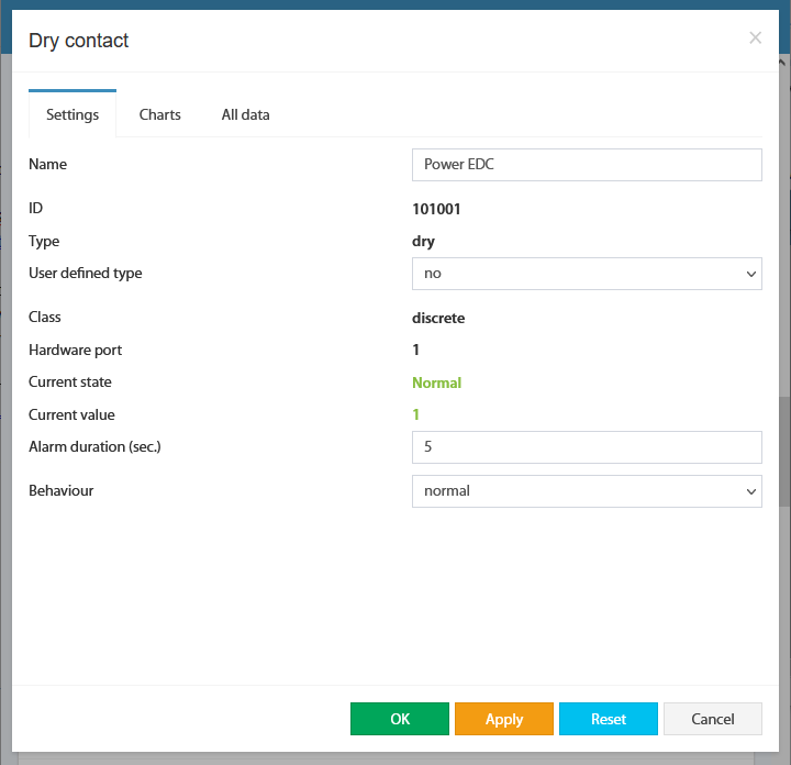
For internal contacts, you can specify the type of behavior (normal or reversive) and specify the type of input. "User-defined type" only affects the icon in the interface. Types can be the following: airflow, door, motion, smoke, vibration, water, and no special type (by default).
For dry contacts on the CAN bus, "Alarm" duration control is also available. This holds on an active level when the signal is already removed from the input. This allows you to suppress the instability of the input signal, if necessary.
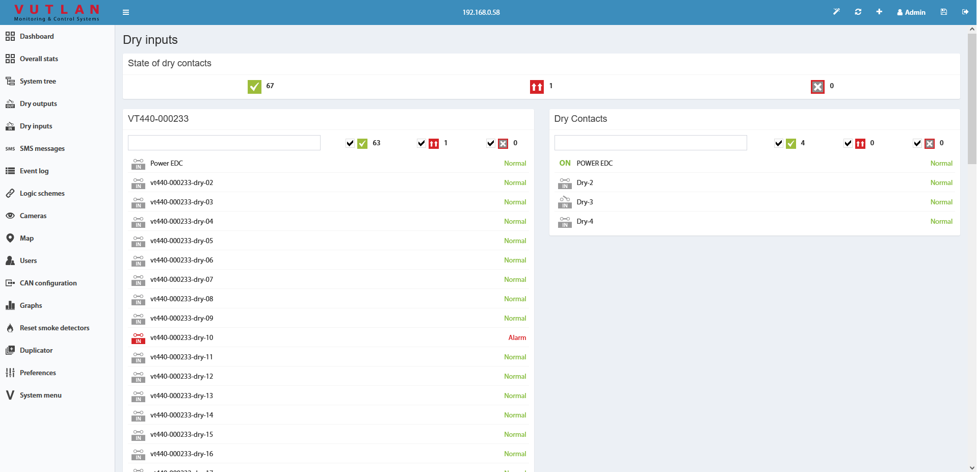
The dry contacts window is designed to control dry contacts of internal dry inputs, VT440, VT16, and other extensions. The general view is shown here:
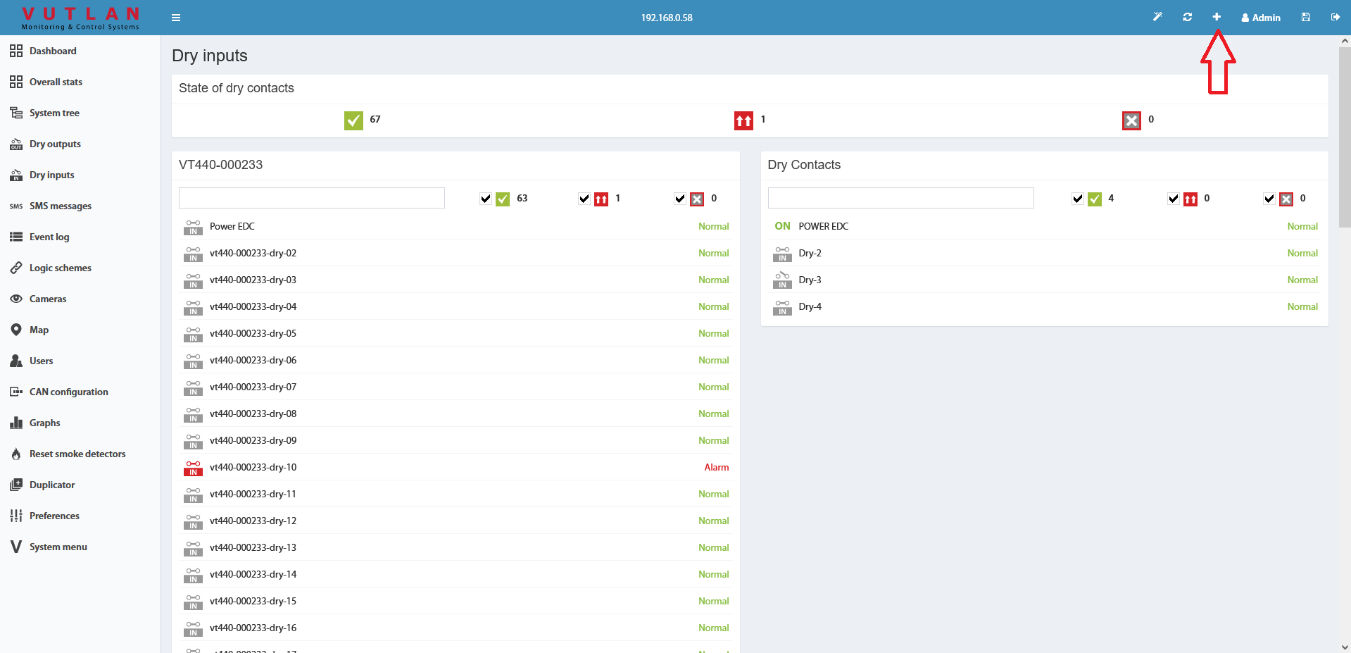
To create the logic for an arbitrary group of contacts press the button " " in the upper left corner. This starts with a wizard creating a logic circuit.
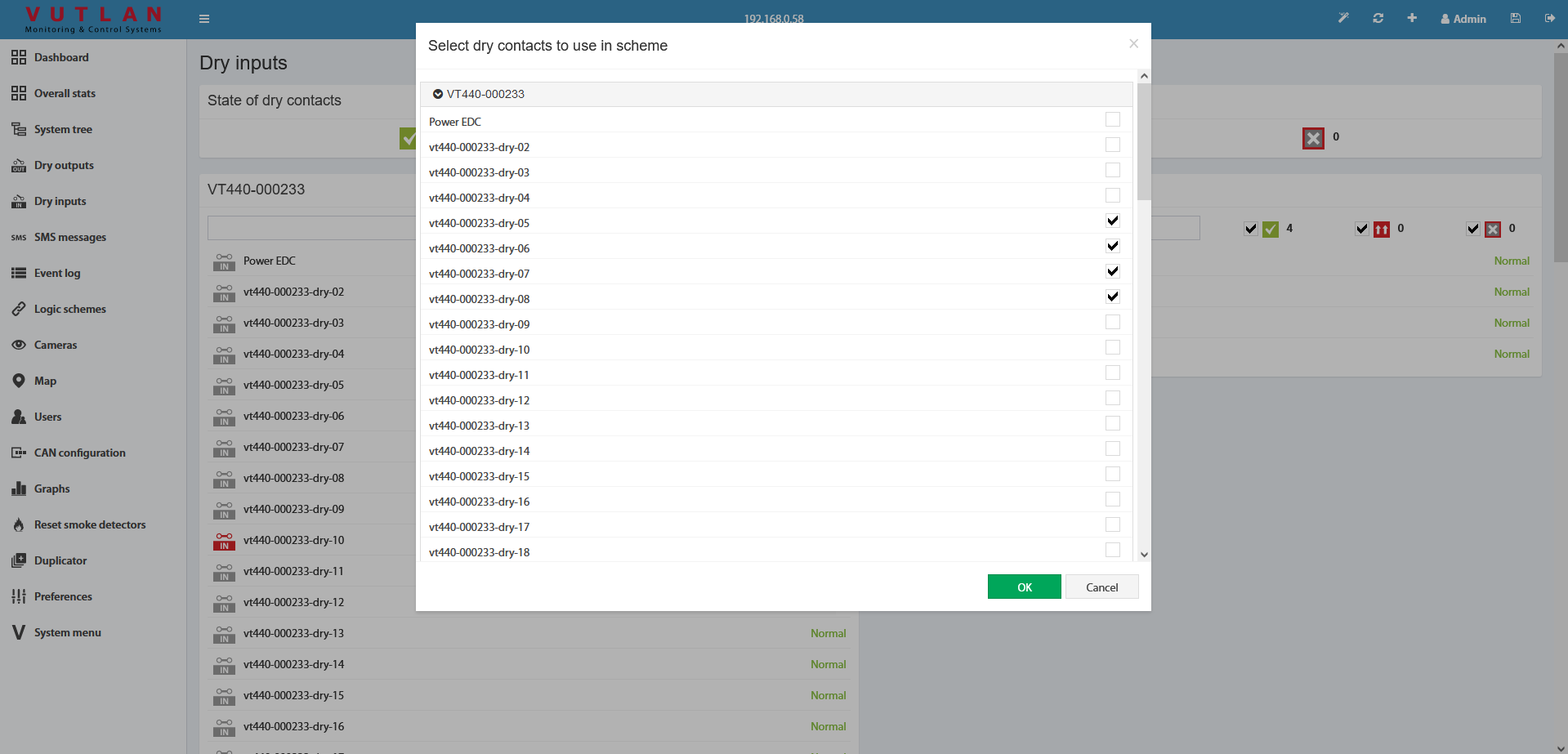
As the first step of the wizard, you must select the dry contacts to create a logical scheme.
After you click OK, you are prompted to create a trigger.
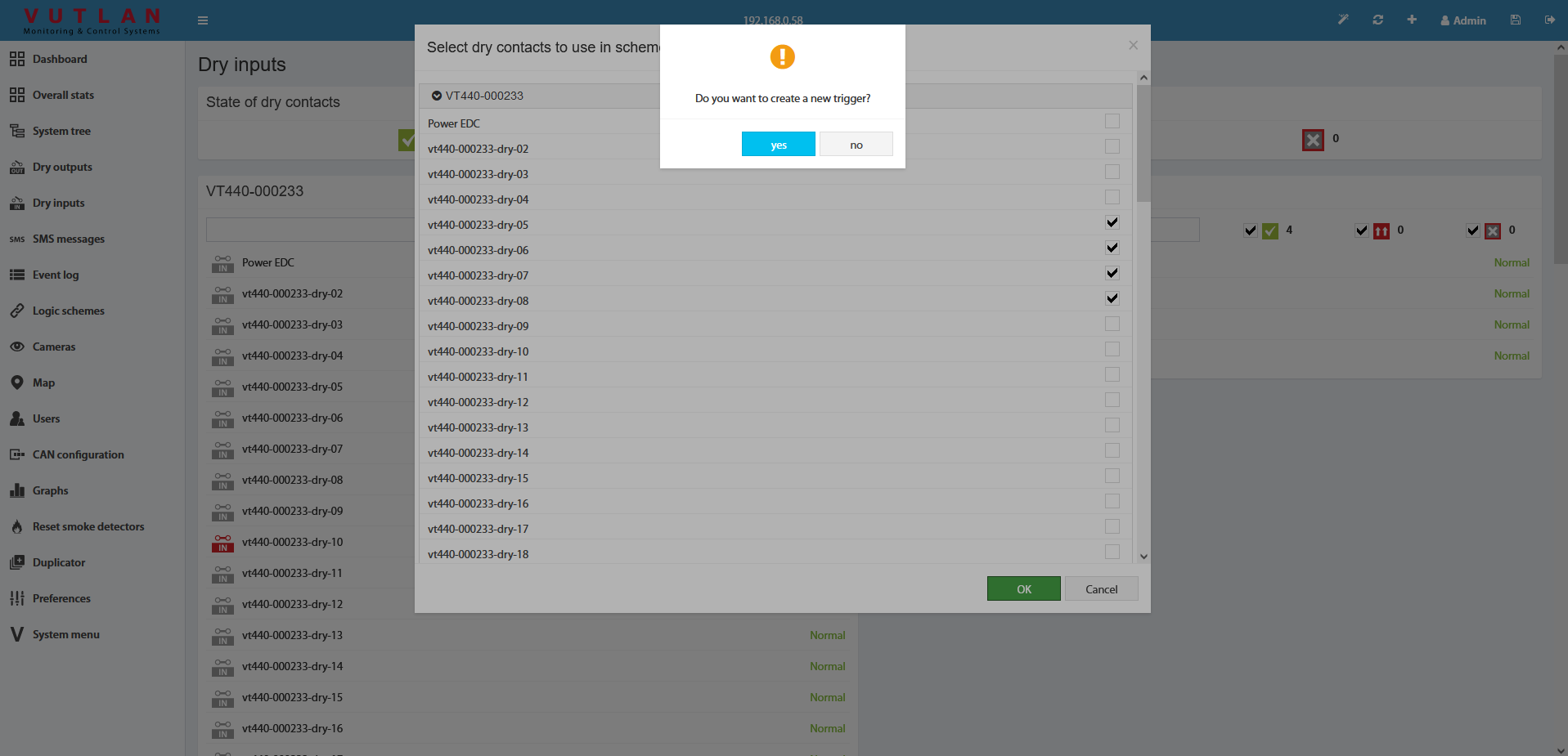
The trigger can be not created. But in this case, in "THEN" the logic circuit can be used only existing elements.
As the last step, you need to edit and create a logic circuit with the OK button.

Do not forget to save all new settings and logic schemes into flash memory by clicking " " in the right top corner of the interface!
Frequently asked questions
Question | Answer |
|---|---|
What is the effective “max” distance that could be realistically supported to monitor Dry contacts? | Very long distances. Two kilometers are easily supported. |
|
|
Copyright:
Vutlan s.r.o. (LLC)
Remote Infrastructure Monitoring and Control
43 ul.Svornosti, 821 06 Bratislava,
Slovak Republic
Configuration
Dry contacts
Other pages of interest include: "Connecting dry contacts inputs".
For internal contacts, you can specify the type of behavior (normal or reversive) and specify the type of input. "User-defined type" only affects the icon in the interface. Types can be the following: airflow, door, motion, smoke, vibration, water, and no special type (by default).
For dry contacts on the CAN bus, "Alarm" duration control is also available. This holds on an active level when the signal is already removed from the input. This allows you to suppress the instability of the input signal, if necessary.
The dry contacts window is designed to control dry contacts of internal dry inputs, VT440, VT16, and other extensions. The general view is shown here:
To create the logic for an arbitrary group of contacts press the button "" in the upper left corner. This starts with a wizard creating a logic circuit.
As the first step of the wizard, you must select the dry contacts to create a logical scheme.
After you click OK, you are prompted to create a trigger.
The trigger can be not created. But in this case, in "THEN" the logic circuit can be used only existing elements.
As the last step, you need to edit and create a logic circuit with the OK button.
Do not forget to save all new settings and logic schemes into flash memory by clicking "" in the right top corner of the interface!
Relay switching
Outlets switching for all units can do in a "System tree" of the Web Interface.
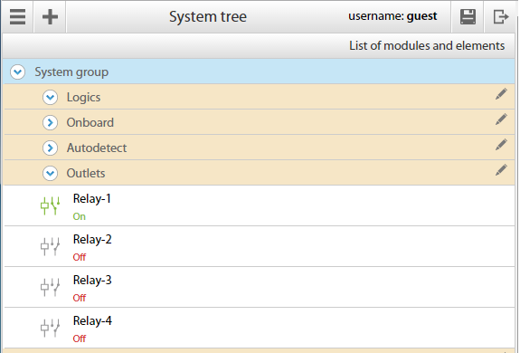
To switch on/off all relays for all units go to the "Main menu" " " >> "System Tree">> Choose a "Relay" element you want to configure and click on it >> A modal window with properties will pop up:
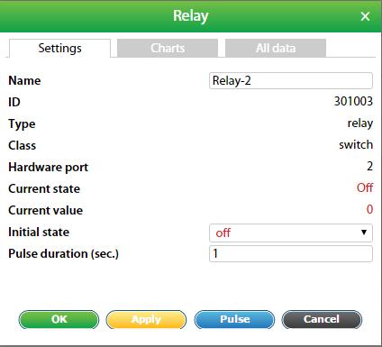
1 | Name | Relay-# by default. Can be changed. |
2 | Group | A group can be selected for visual display in the "Group tree" menu |
3 | Hardware port | Port 1 = relay 1/outlet 1; port 2 = relay 2/outlet 2 and so on. |
4 | Current state | Shows current state of the relay |
5 | Current value |
|
6 | Initial state |
|
7 | New state |
|
8 | Pulse duration | Measured in seconds. 1-second minimum. |
Example: The relay is "Off". Let's say we need to switch it "On" for 30 seconds. In the field "New state" choose "Pulse"; specify "Pulse duration" for 30 sec. Then press "Apply" or "Save". The relay will switch to the "On" state for 30 seconds. Then it will return to the "Off" state.
Outlets switching
To start managing relay switching of VT604 or VT608 units, go to "Main menu" "" >> "Outlets" menu. You should see the outlets:
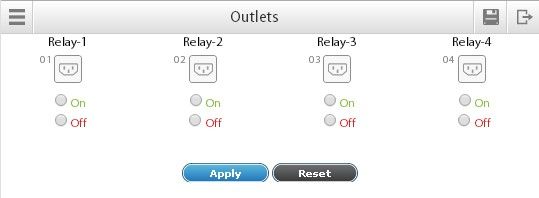
First, choose which outlets you need to switch to "On" or "Off" state, then press "Apply". The interface window will update itself in a moment:
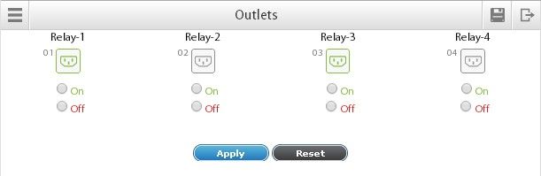
For the picture above, we've switched "On" Relay-1 (Outlet-1) and Relay-3 (Outlet-2). They are highlighted in green color. Outlet-2 and Outlet-4 are currently off.
It is possible to manage each outlet individually. For that go to "  " >> "Group tree" or "System tree" menu >> click on any of the four relays.
The "Pulse" parameter always changes relay's state to an opposite state.