VT10 / 1-Wire board
- Vladimir Tayzhev
- Admin1
- Vasily T.
![]() End of Life: 31.10.2022
End of Life: 31.10.2022
.jpg?version=1&modificationDate=1632907512940&cacheVersion=1&api=v2&width=300&height=184)
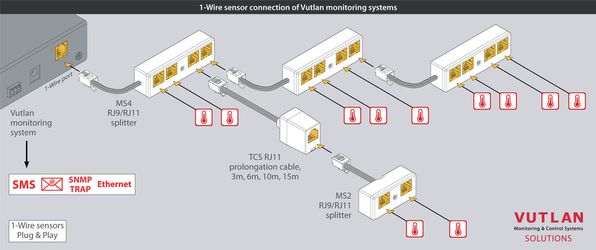
It is possible to connect up to two readers to one Vutlan monitoring system. Please use a splitter to do this. In such a case both readers are seen by the system as one reader. This is useful when one reader is used for entrance and one reader for the exit of the same door.
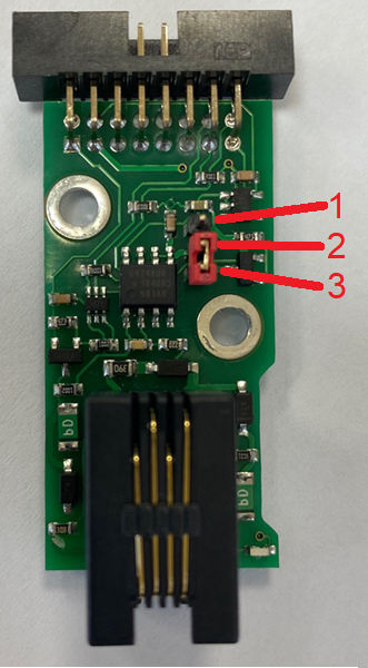
When "VT10" is installed inside of monitoring unit, "VT10" looks like this:
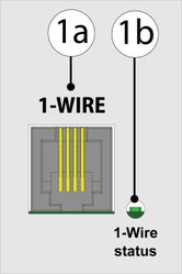
1a. RJ9 jack for connecting 1-Wire sensors.
1b. Green LED. If the green light is "ON", then the 1-Wire board is on. There's an element inside the monitoring unit's interface that can be switched "ON" and "OFF", which activates the 1-Wire bus.
Technical specifications
Feature | Description |
|---|---|
| Product dimensions | Length 44mm, Width 23mm, Height 15mm |
| Inputs terminals | RJ9 4P4C |
| Network Interface | 1-Wire |
| Status Indicators | 1-Wire status LED |
| Operating temperature | Temperature: Min. -10° C - Max.+80° C |
| Other | 1- Wire sensors are plug-&-playVT10 needs to be activated (On/Off) inside the interface. |
| Packing size | (Length, Width, Height) 45x45x120 mm |
| Manufactured in (country) | Manufactured in Slovak Republic, E.U. |
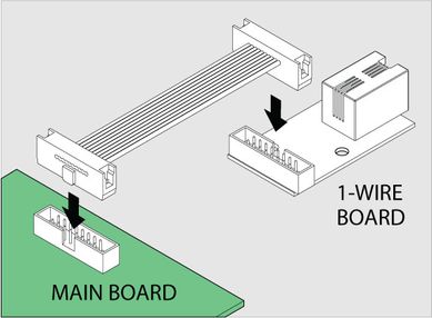
Connection
Monitoring units have the option of installing a "VT10 / 1-Wire board" (expansion board). The board is mounted and connected inside the monitoring unit. 1-Wire technology is based on a serial communication protocol that uses one data line and a reference ground between the master (for example, the VT335 / Monitoring Unit) and one wire slave.
Installation and connecting of VT10 1-Wire board
To install and connect extension units: switch off the appliance, unplug from the outlet or disconnect the power connector.
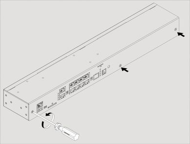
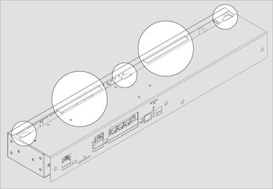
| 1 | Carefully unscrew screws holding the cover and open it. Depending on the monitoring system, it may have 1-Wire, Antenna, GSM, or Dry Contacts, or any other additional modules installed inside. Carefully open the box by unplugging, if necessary, any cables that connect from the top cover to the bottom cover. | |
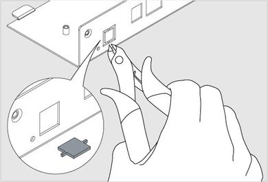
| 2 | Break 2 steel bridges in the 1-Wire hole of the appliance case (e.g. VT335 top metal)cover. Using forceps (cutter) with thin nozzles cut the thin bridges in the hole. Make sure that no burrs are left. | |
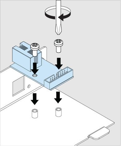
| 3 | Set up the 1-Wire board on 2 steel spacing sleeves inside the appliance case (e.g. VT335 top metal cover), attach the board with two M3 screws from supply to the sleeves. | |
| 4 |
| Connect "16 wire IDC16 flat cable" supplied with a "1-Wire extension" board to the connector on the 1-Wire board and the mainboard (e.g. VT335 board). Make sure is installed in 2-3 position |
| 6 | Close and fasten the cover. Carefully place the top cover back so that all cover wings fit in and all cutoff points match the panel holes. |
Activating 1-Wire interface:
After the "VT10 / 1-Wire board" has been installed inside the system, You need to check if the 1-Wire interface is On.
This page includes: Read articles: Connecting 1-Wire devices and VT10 / 1-Wire board After the "VT10 / 1-Wire board" has been installed inside the system, a new system group should appear inside the monitoring unit's user interface: System tree >> System group>> "1wire". The 1-Wire bus should have "Initial state" switched to "On". In such a case all the 1-Wire sensors connected to "VT10" should appear inside the unit's system tree. In the picture above we see that the 1-Wire temperature sensor is connected to the 1-Wire bus. The configuration of 1-Wire sensors is identical to the configuration of analog sensors. Please, read the article for further info: Sensor configurationConnecting "VT10 / 1-Wire board"
Setting up 1-Wire inside the user interface


Connecting 1-Wire sensors:
All 1-Wire sensors are Plug&Play. Use the following examples for instructions on how to connect sensors:
Example 1:
.jpg?version=1&modificationDate=1526027076108&cacheVersion=1&api=v2&width=645&height=250)
Example 2:
№ | Device | Description |
|---|---|---|
1 | 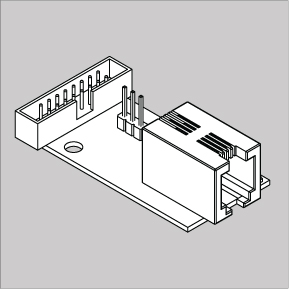 | VT10 / 1-Wire Board |
2 | 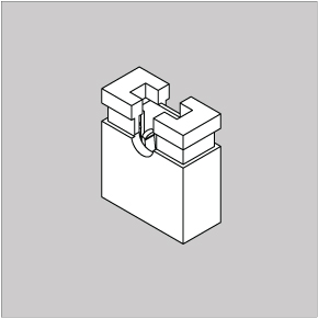 | Jumper step 2mm |
3 | 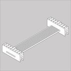 | Cable IDC16 2mm |
4 | 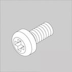 | M3*6 screws. 2 pcs. |
Accessories:
The following accessories can be used with the 1-Wire interface. Accessories are ordered separately.