Documentation page: https://vutlan.atlassian.net/wiki/spaces/DEN/pages/2713911301/VT825i+VT825ii+Data+Center+Monitoring+Unit
Product page: https://vutlan.com/devices/162-55-vt825i-remote-monitoring-unit.html
Drivers: Latest Vutlan drivers for VT855i series (VT335i, VT825i, VT855i)
.png?version=1&modificationDate=1666700713250&cacheVersion=1&api=v2)
.png?version=1&modificationDate=1666700724674&cacheVersion=1&api=v2)
Function and purpose
The unit is used for environmental monitoring (e.g. temperature, humidity, voltage, leakage, smoke, airflow). It is also used as an I/O controller (e.g. door control, fans, generator, control panels, UPS, circuit breakers, and alarms). Can use up to 1000 different elements - notifications, triggers, timers, logic schemes, sensors, dry contacts. Has a built-in Web interface with virtual sensors, logic schemes, different types of notifications, and control panels. Has a slot for an LTE modem for an ethernet connection reservation.
Order options / Dimensions
System | Description |
|---|---|
VT825i | x1 230V AC power inlet. |
VT825ii | x2 230V AC power inlets, providing a redundant power supply for A&B power distribution. |
VT825iDC | x1 230V AC power inlet and x1 24-48V DC power inputs. |
VT825DC | x1 24-48V DC power input. |
VT825DCDC | x2 24-48V DC power input. |
VT825i-12V | x1 230V AC power inlet & x1 12V DC power inlet |
VT825DC-12V | x1 24-48V DC power input & x1 12V DC power inlet |
System | Diagram |
|---|---|
VT825i | 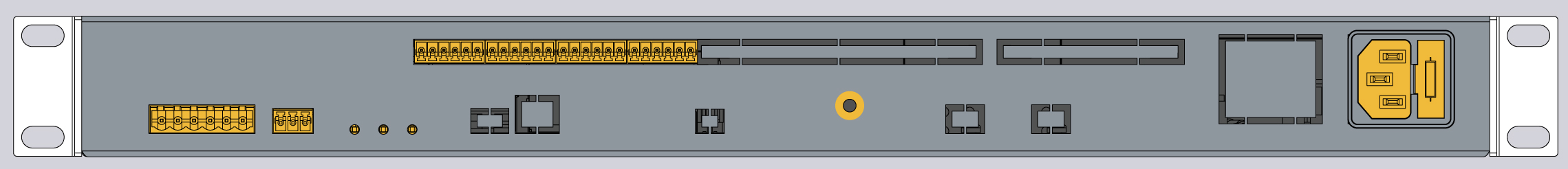 |
VT825ii | 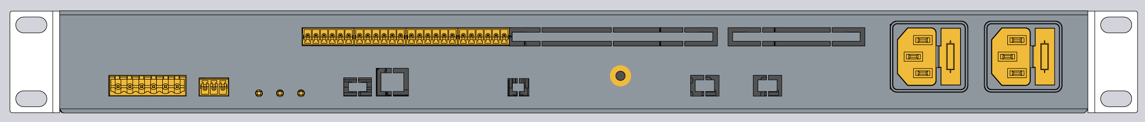 |
VT825iDC | 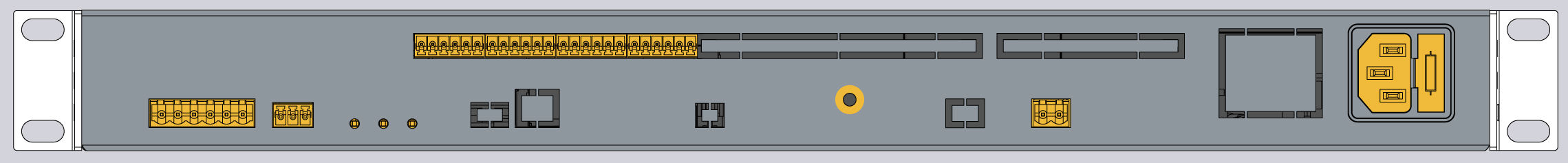 |
VT825DC |  |
VT825DCDC | 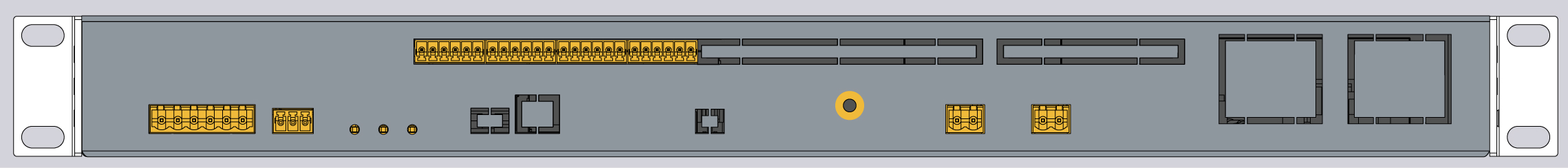 |
Physical Description
Front panel:
.jpg?version=1&modificationDate=1666788508472&cacheVersion=1&api=v2)
Back panel:
.jpg?version=1&modificationDate=1666788508807&cacheVersion=1&api=v2&width=680&height=116)
1. "1U 19-inch brackets" - x2 pcs for mounting brackets into a 1U 19" rack slot.
2. "Logo sticker" - Displays the article number of the monitoring unit.
3. "Sticker space" - A place for a sticker, can be used by a user to place an identifier of the system (for example, an IP address).
4. "Analog sensors: A1..A8" - 8 RJ12 analog sensor inputs with auto-sensing. Read instructions at "Analog sensors connection", and "Sensor configuration".
5. "LAN port" - Ethernet 10/100 Base-T port, provides an Ethernet connection. Read more in this section "LAN, GSM, LTE, RADIUS, DNS, SSL, VPN".
"Orange LED" - orange LED for Ethernet port. It shows network traffic.
"Green LED" - green LED for Ethernet port. It shows network traffic. Flashes green when the system starts up. Shows the connection state (constant green light - the connection is established, blinking green - the connection attempt).
6. "Modem slot" - "VT740 / LTE slot modem" can be installed in this slot. This modem is ordered separately. Read instructions at "VT740 / LTE slot modem", and "LAN, GSM, LTE, RADIUS, DNS, SSL, VPN".
7. USB ports are needed for USB camera recording, USB Flash for system logs, and system restoration. Read instructions at "Connecting USB camera", "USB camera settings. How to save a video", "Saving system logs on USB flash drive", and "USB upgrade or restore of default settings".
a. "USB 0" - type micro USB-port 2.0, required to connect a USB camera.
b. "USB 1" - type USB-port 2.0, required to connect a USB camera or a USB Flash card.
8. "SD card" - MicroSD card slot with an ejector. The card is needed for data storage or the "system restore". Read instructions at "Saving system logs to SD card", and "Restore of the appliance (for VT960 series)".
9a. "CAN DEVICES" - digital connector RJ12 for the connection of CAN sensors/extensions/devices on a CAN bus. Modules can be chained together. Read the instructions at "CAN devises connection", and "Setting up CAN".
"LED: CAN" - green LED indicates CAN bus status.
The LED blinks slowly - nothing is connected
The LED blinks fast - configuration is in process
The LED glows constantly - connected to CAN devices
11. "TEMPERATURE SENSOR" - accuracy +/- 1 °C.
12. "LED: ACT" - green LED indicates appliance system status,
- operating mode of the device: switches at a frequency of 2 times per second;
- successful completion of the software update process: switches at a frequency of 4 times per second;
"LED: ALARM" - The LED can be programmed from the interface for alarm indication.
"LED: ERR" - red LED indicates error and traffic.
the operating mode of the device: If everything is normal, the LED is extinguished, if not - there's a constant glow;
software update mode: switches at a rate of 2 times per second;
13. “Dip switch"
Normal mode: The switch is switched to the left ←. The switch should be always in this position.
Restore of appliance: The switch is switched to the right →. Used to load the clean system image from an SD card. Read instructions at “Restore of appliance (for VT335i, VT825i, VT855i, VT960i & VT960ii series and VT855t series)”.
14a. "OUTPUTS 12V 0.25A" - 12V 0.25A (for each output) terminals outputs (electronic relay). Read the instructions at "Connecting 12V devices to 12V outputs".
"LEDs: E1, E2" - status indicators for two 12V 0.25A outputs.
The LED is ON (orange) - the output is ON (the initial state can be configured).
The LED is OFF (orange) - the output is OFF ((the initial state can be configured).
15. "Relays 1, Relay 2" - NC / NO power relay terminals. Read instructions at "Connecting NC/NO relays", "A relay switching (NC NO)", and "Relays (Outlets) (SNMP)".
"LEDs: R1, R2" - status indicators for x2 relays at the back of the unit.
The LED is ON (orange) - the relay is ON (the initial state can be configured).
The LED is OFF (orange) - the output is OFF ((the initial state can be configured).
16. "DRY CONTACT INPUTS 1...16" - Digital inputs (Type IN). Read the instructions at "Connecting dry contacts", and "Dry contacts settings".
19. Please refer to the section "Order options" in this document.
18. "RESERVE" - Reserve power inlet. 100-240VAC, 50/60Hz, Fuse 2A, Fuse 5x20mm, type C14.
19. "MAIN" - Power inlet. 100-240VAC, 50/60Hz, Fuse 2A, Fuse 5x20mm, type C14.
20. Buttons
20a. "Restart" - the button restarts the appliance. Hold the button for 2 seconds and then let go, and the system will restart.
20b. "Reset settings" - reset settings to default factory settings. Keep pressing the button for more than 5 seconds. The “ERR” LED will start blinking. This indicates that the factory restoration has started. Wait for 20-60 seconds for the system to restart. The “ACT” LED will start blinking once the system has been restarted. The device can be accessed now.
20c. "Factory reset" - Do not use this button.
22. "DC 12V BACKUP POWER" - optional order option. Only available for custom orders.
23. "Chassis grounding" - Chassis grounding, M4 thread. Enhances the immunity of the equipment against conducted and radiated RF disturbances. Please contact a professional electrician before connecting it.
24. "POWER 24-48V DC" - optional order option for some of the units. Please refer to the section "Order options" in this document.
24a. "RESERVE" - Reserve power inlet. 24-48V DC, 5.08mm 2EDGK power plug, 18-72VDC to 12VDC/0.84A
24b. "MAIN" - Power inlet. 24-48V DC, 5.08mm 2EDGK power plug, 18-72VDC to 12VDC/0.84A
Connection overview diagram
The front panel of VT825i & VT825ii:

The back panel of VT825ii:

Drawing dimensions
.jpg?version=1&modificationDate=1666854508786&cacheVersion=1&api=v2)
Installing the device into a 19" rack
Use x3 pcs of supplied screws (M3 6mm) for each bracket to fix it on each side of the enclosure as shown in the picture below. The screws and brackets are supplied with the unit.


Installing a backup battery
It is possible to attach a backup battery holder for a battery at the back of the system.
VT101i product page: https://vutlan.com/mounting-brackets-holders/170-vt101i-battery-holder.html
CL-18650-29E/3S1P: https://www.tme.eu/sk/details/cl-18650-29e_3s1p/akumulatory/cellevia-batteries/
-13.jpg?version=1&modificationDate=1678880626711&cacheVersion=1&api=v2)
Installing LTE slot modem
Inventory
Make sure that the contents of the delivery meet the following configuration. Report a missing or damaged component to your supplier. If damage occurred during transportation, contact the appropriate delivery service.
Package content | Description | Quantity | |||||
|---|---|---|---|---|---|---|---|
VT825i | VT825ii | VT825iDC | VT825DC | VT825DCDC | |||
1 |  | Monitoring unit VT825i. | 1 pc | ||||
2 |  | OTG Micro USB cable adapter | 1 pc | ||||
3 |  | RJ-45 3m patch cable. For LAN Ethernet connection. | 1 pc | ||||
4 |  | Self-adhesive rubber foot | 4 pcs | ||||
5 |  | 19" rack brackets | 2 pcs | ||||
6 |  | M3 x 8mm Phillips flat-head screws | 6 pcs | ||||
7 | Configuration manual | 1 pc | |||||
8 |  | Warranty card | 1 pc | ||||
9 |  | Terminal plug 6 pins, 5.08mm, 6P. For NC NO COM relays. | 1 pc | ||||
10 |  | Terminal plug 3 pins, 3.81 mm. For 12V relays (E1 & E2). | 1 pcs | ||||
11 |  | Terminal plug 6 pins, 3.5 mm. For connecting dry contact inputs. | 4 pcs | ||||
VT825i | VT825ii | VT825iDC | VT825DC | VT825DCDC | |||
12 |  | Terminal plug 2 pins, 5.08mm, 2P. For power input 24-48VDC. | - | - | 1 pc | 1 pc | 2 pc |
13 |  | EU Schuko C13 0.75 мм2 . 230V 10A cable. | 1 pc | 2 pc | 1 pc | - | - |
14 |  | IEC C13 - C14 230V 10A | - | 2 pc | - | - | - |
Technical details
VT335t, VT336t, VT825t, VT825tt, VT855t, VT855tt, VT960t and VT960tt are the monitoring units and can not connect to each other. For scalability please use extension units and embedded boards.
● Built-in □ None ♦ Extension possible ◊ Not extendable
Versions | |||||
|---|---|---|---|---|---|
Device Management: Web, SNMP | Yes | Yes | Yes | Yes | Yes |
Sensor access: Three-level by login | Yes | Yes | Yes | Yes | Yes |
Interface | |||||
LAN: Ethernet 10/100 Mbit | Yes | Yes | Yes | Yes | Yes |
OS: Linux | v.6.2 | v.6.2 | v.6.2 | v.6.2 | v.6.2 |
Interface: Any browser | Yes | Yes | Yes | Yes | Yes |
Memory RAM: | 128 Mb | 128 Mb | 128 Mb | 128 Mb | 128 Mb |
CPU speed: | 1 GHz | 720 MHz | 720 MHz | 720 MHz | 600 MHz |
Total CPU cores: | 2 | 2 | 2 | 2 | 2 |
Clock: Built-in clock | Yes | Yes | Yes | Yes | Yes |
Timer: Built-in watchdog | Yes | Yes | Yes | Yes | Yes |
The maximum amount of sensors: physical sensors, dry contacts, relays | 150 | 130 | 100 | 100 | 100 |
The maximum amount of elements: notifications, triggers, timers, logic, sensors, dry contacts, SNMP Get, SNMP Trap, Dial task, and other elements | 1000 | 1000 | 700 | 700 | 700 |
Networking / Protocol support | |||||
LTE Gateway mode: Internet access (routing for internal network) (modem ordered separately) | Yes | Yes | Yes | Yes | No |
LTE Access mode: Internet access over LTE (modem ordered separately) | Yes | Yes | Yes | Yes | No |
Network protocols: DHCP; HTTP; HTTPS; SNMP v1, v2c, v3; SMTP; FTP; Syslog; TLS; | Yes | Yes | Yes | Yes | Yes |
Modbus RTU | Using extension VT485m | Using extension VT485m | Using extension VT485m | Using extension VT485m | No |
RS485 / OSDPv2: reader access control | Yes | Yes | Yes | Yes | No |
Modbus TCP / IP | Yes | Yes | Yes | Yes | Yes |
Static routing | Yes | Yes | Yes | Yes | |
Dynamic DynDNS | Yes | Yes | Yes | Yes | Yes |
Access via RADIUS server | Yes | Yes | Yes | Yes | Yes |
VPN: secure data communications; secure change of connection between LTE and LAN | Yes | Yes | Yes | Yes | No |
SSL installation | Yes | Yes | Yes | Yes | Yes |
NTP server | Yes | Yes | Yes | Yes | Yes |
Alerts / Notifications | |||||
Alert types: E-mail, FTP log, Syslog, SMTP, SNMP Traps, SMS (Modem is ordered separately), Web-to-SMS, | Yes | Yes | Yes | Yes | Yes |
A maximum number of "mail to" recipients in an E-mail notification: | 20 | 20 | 20 | 20 | 20 |
A maximum number of "SMS to" recipients in an SMS notification: also the maximum amount of phone numbers | 20 | 20 | 20 | 20 | |
Virtual sensors | |||||
Pings: Built-in function for server pinging. Test the reachability of a host in a network. | Yes | Yes | Yes | Yes | Yes |
IP cameras: Connect the IP MJPEG camera with a proxy via the master module. Only view, no record. | 4 | 4 | 4 | 4 | 4 |
Get SNMP: Read data from external equipment via SNMP PDU GET (v1/2c) | Yes | Yes | Yes | Yes | Yes |
User keys: Add users who have access using an RFID reader. | Yes | Yes | Yes | Yes | No |
Logic schemes: Used to specify automatic actions to events that occur in the system. | Yes | Yes | Yes | Yes | Yes |
Timers: Allows you to plan the events in the system. | Yes | Yes | Yes | Yes | Yes |
Triggers: Generate events in the system if logic is triggered. | Yes | Yes | Yes | Yes | Yes |
SNMP traps | Yes | Yes | Yes | Yes | Yes |
Virtual Math element (combine several sensor data and calculate new data) | Yes | Yes | Yes | Yes | Yes |
Logic schemes | Yes | Yes | Yes | Yes | Yes |
Modbus TCP/IP: read/write | Yes | Yes | Yes | Yes | Yes |
Power | |||||
Power input (230V AC): | x2 inputs option | x2 inputs option | No | No | No |
Power input (24 ÷ 48V DC): | x2 inputs option | x2 inputs option | No | No | No |
Power input (12V DC): | x1 input option | x1 input option | x2 inputs | x2 inputs | Input |
Fuse: Fuse at the inlet | 1 A | 1 A | PTC | PTC | PTC |
Min. power consumption: | 1 W | 1 W | 1 W | 1 W | 1 W |
Max. power consumption: | 10 W | 10 W | 10 W | 10 W | 6 W |
The maximum current load on the relay: | 10А | 10А | 250mА | 250mА | 250mА |
Redundant power supply: built-in voltage monitor, voltage range 9-12.6V. | Yes AC/DC DC/DC | Yes AC/DC DC/DC | Yes DC/DC | Yes DC 12V | - |
Outputs | |||||
Relay outputs: latching relays 240V*10A | 2 | 2 | - | - | - |
Relays outputs: 12V 0.25A | 2 | 2 | 2 | 2 | 2 |
Max. dry contact outputs (contact closures/digital outputs) | 8 | - | 5 | - | - |
Inputs | |||||
Analog port: 6P6C for connection of an analog sensor. (extendable using CAN bus) | 8 built-in ports, extended using extension unit | 8 built-in ports, extended using extension unit | 4 built-in ports, | 4 built-in ports, extended using extension unit | 4 built-in ports, extended using extension unit |
CAN port: Max number of sensors Use CAN-12V-1A for connecting more than 12 devices. | x2 port, x32 devices in total | x1 port, max. 32 devices | x1 port, max. 32 devices | x1 port, max. 32 devices | x1 port, max. 10 devices |
Dry contact inputs: (contact closures/digital inputs) | 32 | 16 | 8 | 4 | 2 |
Modbus RTU (RS-485): Max. line length 1000m | Using extension VT485m | Using extension VT485m | Using extension VT485m | Using extension VT485m | - |
OSDP v2 reader extension: | Using extension VT485R | Using extension VT485R | Using extension VT485R | Using extension VT485R | - |
Video | |||||
USB cameras | x1 | x1 | x1 | x1 | x1 |
IP cameras | x4 | x4 | x4 | x4 | x4 |
RTSP IP camera | - | - | - | - | - |
Other connectors | |||||
Ethernet port: 10/100Mbit | x1 | x1 | x1 | x1 | x1 |
Ethernet port: 10/100/1000Mit | - | - | - | - | - |
USB 2.0 Type A | - | - | - | - | - |
USB 2.0 micro | x1 | x1 | x1 | x1 | x1 |
Switch Normal / Recovery: returns the device to factory settings | Yes | Yes | Yes | Yes | Yes |
External Memory / Logs | |||||
Micro SD memory card slot (SDXC up to 512 Gb) | Yes | Yes | Yes | Yes | Yes |
SD card formatting function (FAT32) | Yes | Yes | Yes | Yes | Yes |
USB flash drive: logs, sensor readings, item settings, etc. | Yes | Yes | Yes | Yes | Yes |
Send system log to e-mail: Logs, sensor data, elements settings, etc. | Yes | Yes | Yes | Yes | Yes |
Sensor dump files: save the per-second samples of analog and discrete sensors | Yes | Yes | Yes | Yes | Yes |
Yes | Yes | Yes | Yes | Yes | |
Send to FTP server: Logs, sensor data, elements settings, etc. | Yes | Yes | Yes | Yes | Yes |
Maximum amount of log files: 10,000 logs/days = 27 years | Yes | Yes | Yes | Yes | Yes |
Sample rate/period (logs, graphs) | 1 s | 1 s | 1 s | 1 s | 1 s |
Modem (extension ordered separately) | |||||
4G LTE modem: ordered separately. | - | ||||
Modem modes:
| Gateway / Access / SMS | Gateway / Access / SMS | Gateway / Access / SMS | Gateway / Access / SMS | - |
Modem LED: STATUS | Yes | Yes | Yes | Yes | - |
Embedded onboard sensors | |||||
Temperature sensor: +/- 1 °C PCB temperature. | Yes | Yes | Yes | Yes | Yes |
Power supply voltage sensor: Accuracy (1%) | Main & Reserve | Main & Reserve | Main & Reserve | Main & Reserve | Yes |
LED indication | |||||
Ethernet LAN: LINK | Yes | Yes | Yes | Yes | Yes |
Ethernet LAN: ACT | Yes | Yes | Yes | Yes | Yes |
CAN bus: STATUS | Yes | Yes | Yes | Yes | Yes |
System: STATUS (ACT) | Yes | Yes | Yes | Yes | Yes |
System: ERROR (ERR) | Yes | Yes | Yes | Yes | Yes |
System: ALARM | Yes | Yes | Yes | Yes | Yes |
12V 0.25A outputs: STATUS (e.g. E1, E2) | x2 | x2 | x2 | x2 | x2 |
MODBUS RTU: STATUS | VT485M | VT485M | VT485M | VT485M | - |
ODSP Reader. | VT485R | VT485R | VT485R | VT485R | - |
NC/NO/COM Relay (e.g. R1, R2) | x2 | x2 | - | - | - |
Environmental characteristics | |||||
Operating temperature: -10 to 80 °C | Yes | Yes | Yes | Yes | Yes |
Storage temperature: –25 to 85 °C | Yes | Yes | Yes | Yes | Yes |
Operating humidity: 0 to 90 %, non-condensing | Yes | Yes | Yes | Yes | Yes |
Storage humidity: 0 to 95 %, non-condensing | Yes | Yes | Yes | Yes | Yes |
Other Features | |||||
Installation: | 19” 1U | 19” 1U | DIN rail, Wall | Desktop | Desktop |
Casing: | Sheet metal | Sheet metal | Plastic | Sheet metal | Plastic |
Dimensions (L x W x H) in mm: | 440x44x90 | 440x44x90 | L_212.5 H_90.1 D_32.20 | 180x35x80 | 150x29x100 |
Weight: | 1,6 kg | 1,5 kg | 0,7 kg | 0,5 kg | |
External chassis grounding: M4 thread | Yes | Yes | Yes | Yes | Yes |
Web interface (panels) | |||||
Dashboard panel: | Yes | Yes | Yes | Yes | Yes |
Overall statistics panel: | Yes | Yes | Yes | Yes | Yes |
System tree panel: sensors and devices displayed in a hierarchy | Yes | Yes | Yes | Yes | Yes |
Dry outputs panel: | Yes | Yes | Yes | No | Yes |
Dry inputs panel: | Yes | Yes | Yes | Yes | Yes |
Event log panel: amount of logs | 300 | 300 | Yes | 300 | 200 |
Logic schemes panel: | Yes | Yes | Yes | Yes | Yes |
Cameras panel: | Yes | Yes | Yes | Yes | Yes |
Map panel: 5 layers | Yes | Yes | Yes | Yes | Yes |
Users panel: | Yes | Yes | Yes | Yes | Yes |
CAN configuration panel: | Yes | Yes | Yes | Yes | Yes |
Graphs panel: | Yes | Yes | Yes | Yes | Yes |
Reset smoke detectors panel: | Yes | Yes | Yes | Yes | Yes |
Preferences panel: Web GUI, Network, Time, Logging, DynDNS, SNMP, RADIUS, FTP backup, VPN Clent, Modbus RTU, GPS, SMTP, Routing | Yes | Yes | Yes | Yes | Yes |
System menu panel: About, Firmware, Export, Support | Yes | Yes | Yes | Yes | Yes |
List of latest sent SMS messages: | 200 | 200 | Yes | 150 | 200 |
Analog sensor power reset: resets smoke sensors | Yes | Yes | Yes | Yes | Yes |
● Built-in □ None ♦ Extension possible ◊ Not extendable
Copyright:
Vutlan s.r.o. (LLC)
Remote Infrastructure Monitoring and Control
43 ul.Svornosti, 821 06 Bratislava,
Slovak Republic