VT416 / DC current monitor
- Vasily T.
- Vladimir Tayzhev
Functional description & components
.jpg?version=1&modificationDate=1554900079998&cacheVersion=1&api=v2&width=500&height=211)
.jpg?version=1&modificationDate=1554900081419&cacheVersion=1&api=v2&width=500&height=211)
Physical description VT416
.jpg?version=1&modificationDate=1554900096709&cacheVersion=1&api=v2&width=800&height=417)
Function
Simple Bidirectional DC current monitor VT416 can measure DC currents in range of ± 6A.
Components
The monitor consists of a plastic housing with two inputs, one with Hall DC current sensor with 4 pins terminal connector and second RJ9 for connection to monitoring system.
.jpg?version=1&modificationDate=1554900090020&cacheVersion=1&api=v2&width=590&height=250)
Safety instructions
- Please observe the valid regulations for installation in the country in which current monitor is installed and operated, and the national regulations for accident prevention. Please also observe any internal company regulations, such as work, operating and safety regulations.
- The technical specifications and limit values stated must not be exceeded under any circumstances. In particular, this applies to the specified ambient temperature range and IP protection category.
Siting location requirements
To ensure proper functionality, the conditions specified in section “Technical specifications” must be observed.
Installation procedure
.jpg?version=1&modificationDate=1554900097697&cacheVersion=1&api=v2&width=600&height=526)
Notes on assembly
- Be careful, sensor max. voltage for isolation is 2kV.
- Inputs on both poles are parallel.
- The monitor can measure DC current on any current wire, not more then 3 mm in diameter.
- Max. distance for DC current transducer from monitoring unit is 50 meters.
Installation
- Mount current monitor using self-adhesive feet or stickers.
- Connect current wires to terminals.
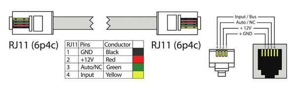
Connection
Connect one end of RJ11 cable to monitoring unit and the other RJ9 end to analog output of current monitor. The monitoring system will automatically sense DC current monitor as a fV sensor.
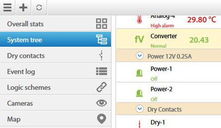
The new sensor will appear in the web interface of the system. Click on "System tree" menu and you will find a new sensor marked by an icon  (abreviation from: Voltage function, used for sensor monitors and converters). Click on the sensor to open it's properties.
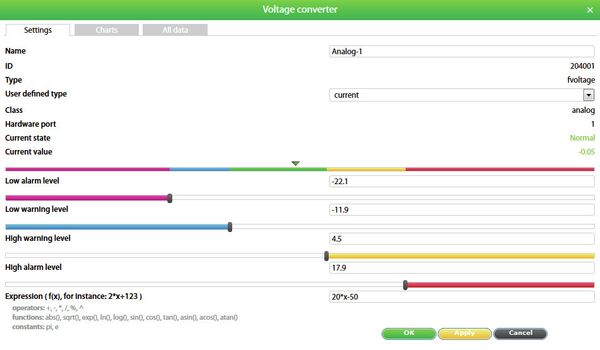
A modal window with sensor properties will pop up.
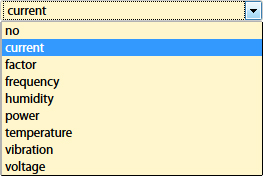
- Change type of the sensor by choosing "Current". Choosing any type of the sensor does not affect sensor properties, it only changes sensor icon for comfort of usage.
- Change the name of sensor, for example "Current".
- Use "Expression formula", for VT416 if initial current I=0 then output V=~2.5V, that means B= ~-2.5; full scale is 5V, 8A=5V and -8A=0V, that means K=3.25. Expr= 3.25*(x-2.5). Please calculate "B" accurate with zero current.
- Put in the threshold levels by dragging: Low alarm, Low warning, High warning, High alarm levels.
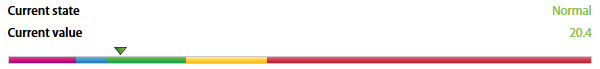
For example, graph above shows that the state of the sensor at the moment is "Normal" because 20.4 is between "Low warning" and "High warning" states, which is considered "Normal" state. - Click “Save” or “Apply” at the bottom of the “Properties” window. The page will reload and the sensor will update by changing it's icon type to
 (abreviation from: "Ampers").
Mounting
a) Wall mounting can be achieved by using stickers supplied in the package.
.jpg?version=1&modificationDate=1554900098681&cacheVersion=1&api=v2&width=300&height=333)
b) Or you can use adhesive legs for putting it on a surface.
.jpg?version=1&modificationDate=1554900095913&cacheVersion=1&api=v2&width=300&height=241)
Technical specifications
VT416 / DC current monitor | |
|---|---|
| Dimensions | Size 102 × 52 x 26 mm |
| Weight | 160 g |
| Inputs | RJ-9 / 2EDGK-7.5 |
| Operating temperature | Min. -10° C - Max.80° C |
| Operating humidity | Min. 5% - Max. 95% (Non-Condensing) |
| Power input | 12V DC |
| Mounting | Desktop, Wall mount |
| Power Consumption | 100 mW |
| Components | Manufactured in EU. |
| Max. distance m | 50 m |
| Special Features | Isolation - 2,5 kV, Measured range ±8 A, Accuracy - 1%, Output 0-5 V. |
| HS Code | 9030 33 100 |