Functional description & components
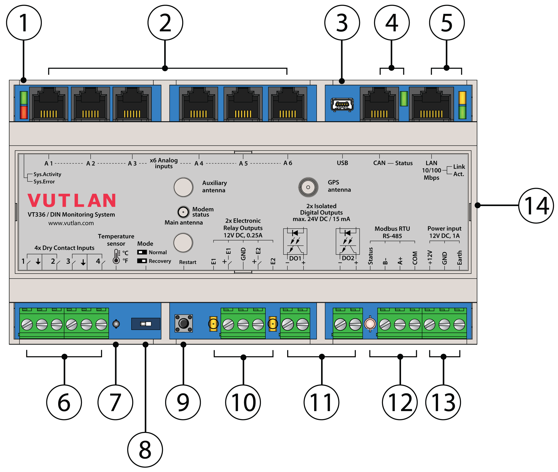
1. "LED: ACTIVITY" - green LED indicates appliance status
"LED: ERROR» - red LED indicates system error and traffic.
2. "Analog sensors: A1..A6" - x6 RJ12 analog sensor inputs with auto-sensing. Read instructions at "Analog sensors connection", "Sensor configuration".
3. "USB" - type miniAB USB-port 2.0, required to connect a USB camera, USB flash, USB hub or to restore an appliance using USB flash.
4. "CAN" - digital connector RJ12 for the connection of CAN sensors and CAN extensions on a CAN bus, with auto-sensing. Read instructions at "CAN devices connection", "Setting up CAN".
- "CAN Status" - LED for digital bus sensors:
- The LED blinks slowly - nothing is connected
- The LED blinks fast - configuration is in process
- The LED glows constantly - connected to CAN devices
5. "LAN port" - Ethernet 10/100 Base-T port, provides an Ethernet connection.
- "LAN Link" - orange LED for Ethernet port. It shows network traffic.
- "LAN Activity" - green LED for Ethernet port. It shows network traffic. Flashes green when the system starts up. Shows the connection state (constant green light - the connection is established, blinking green - the connection attempt).
6. "DRY CONTACT INPUTS 1...4" - Digital inputs. Read instructions at "Connecting dry contacts", "Dry contacts settings".
7. "TEMPERATURE SENSOR" - accuracy +/- 1 °C.
8. "MODE" - a DIP switch for changing system modes.
- Normal mode 🠀: Normal operating state. The system should be always switched to this.
- Recovery 🠂: Turns a recovery mode On. Use this option only in case you need to recover manufacturing settings. Read instructions at "Factory settings recovery".
9. "RESTART" - button restarts the appliance. Press the button for several seconds.
10. "OUTPUT 12V 0.25A" - 12V 0.25A output electronic relay terminal. Read instructions at "Connecting 12V devices to 12V outputs".
11. "ISOLATED DRY CONTACTS OUTPUTS 1...4" - Digital outputs 24VDC / 15mA (type OUT). Read instructions at "Connecting dry contacts", "Dry contacts settings".
12. "RS-485 MODBUS RTU" - port for connecting Modbus RTU / RS-485 sensors and devices. Read instructions at "Connecting Modbus RTU sensors to VT336 & VT336PoE", "Configuring Modbus devices".
- "RS-485 Status" - LED for displaying Modbus RTU port status.
13. "DC 12V 1A" - DC power input. Instructions are in the section below.
14. "Modem" - "VT770 / LTE, GPS modem" is ordered separately. Read instructions at "Connecting VT770 / LTE modem with GNSS", "Network: LAN, GSM, LTE, RADIUS, DNS, SSL, VPN".
- "Modem status" - LED displays modems status.
- "SIM card slot" - Open the top cover to insert a SIM card.
- "GSM, LTE main antenna" - Connect GSM or LTE main antenna.
- "LTE auxiliary antenna" - Connect LTE auxiliary antenna (Auxiliary LTE antenna and antenna output are ordered separately from the modem). It helps to establish a stronger and more stable signal.
- "GPS active antenna" - GPS antenna and antenna output are ordered separately from the modem. Allows to set the time using GPS and shows the location of the device on the map.
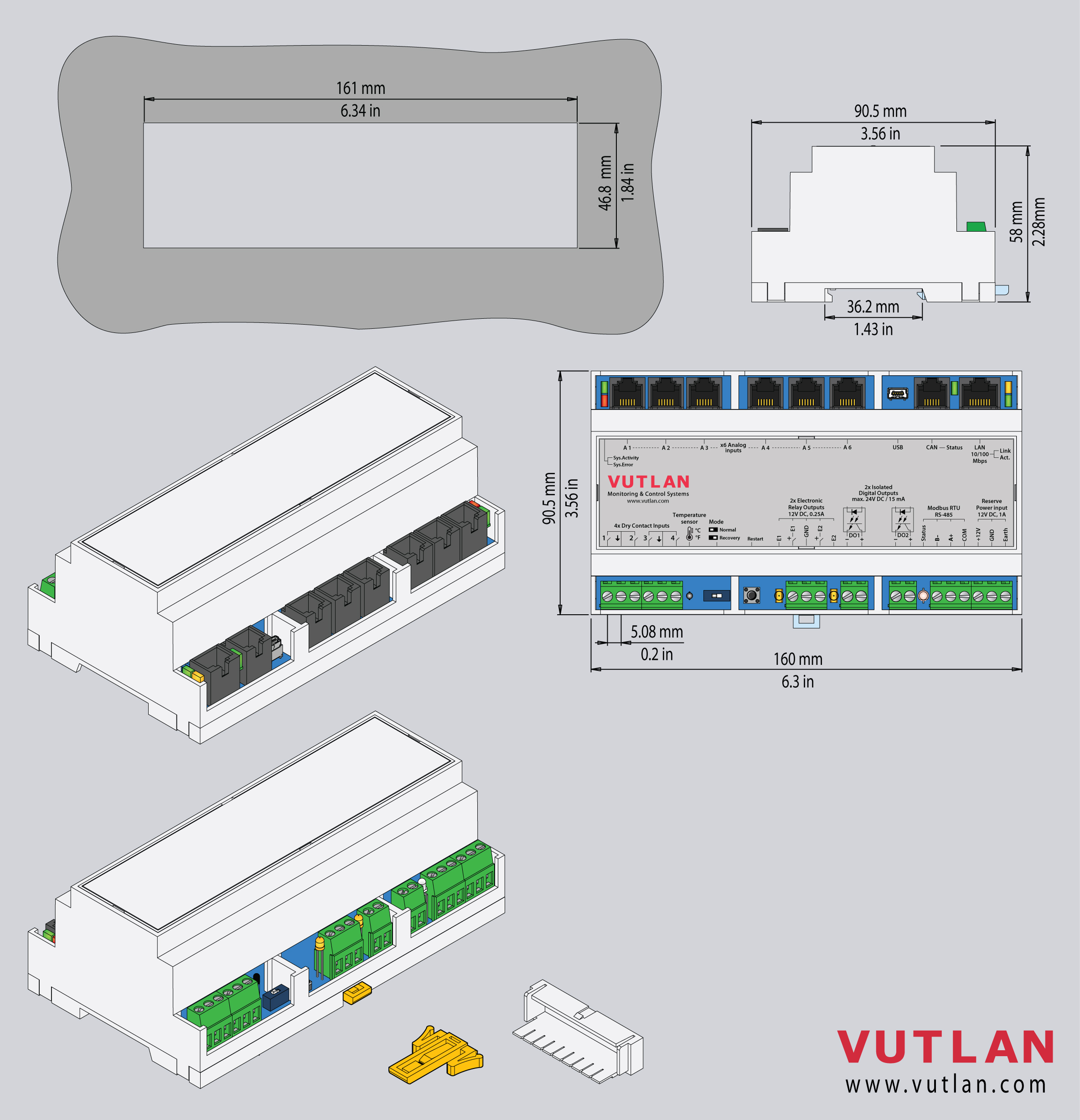
Dimensions
Function & Order options & Technical specifications
Product info is located on the product page "VT336 product page".
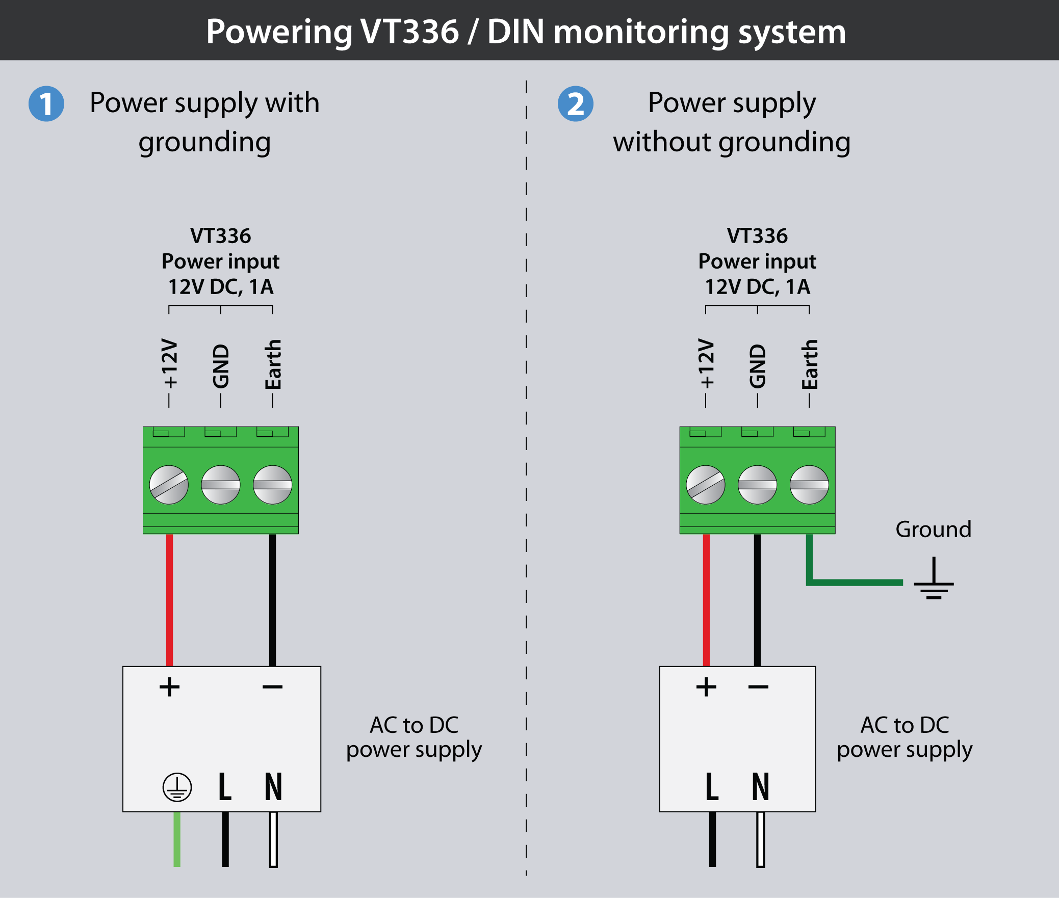
Powering the device
:
Power supply with grounding.
Power supply without grounding.
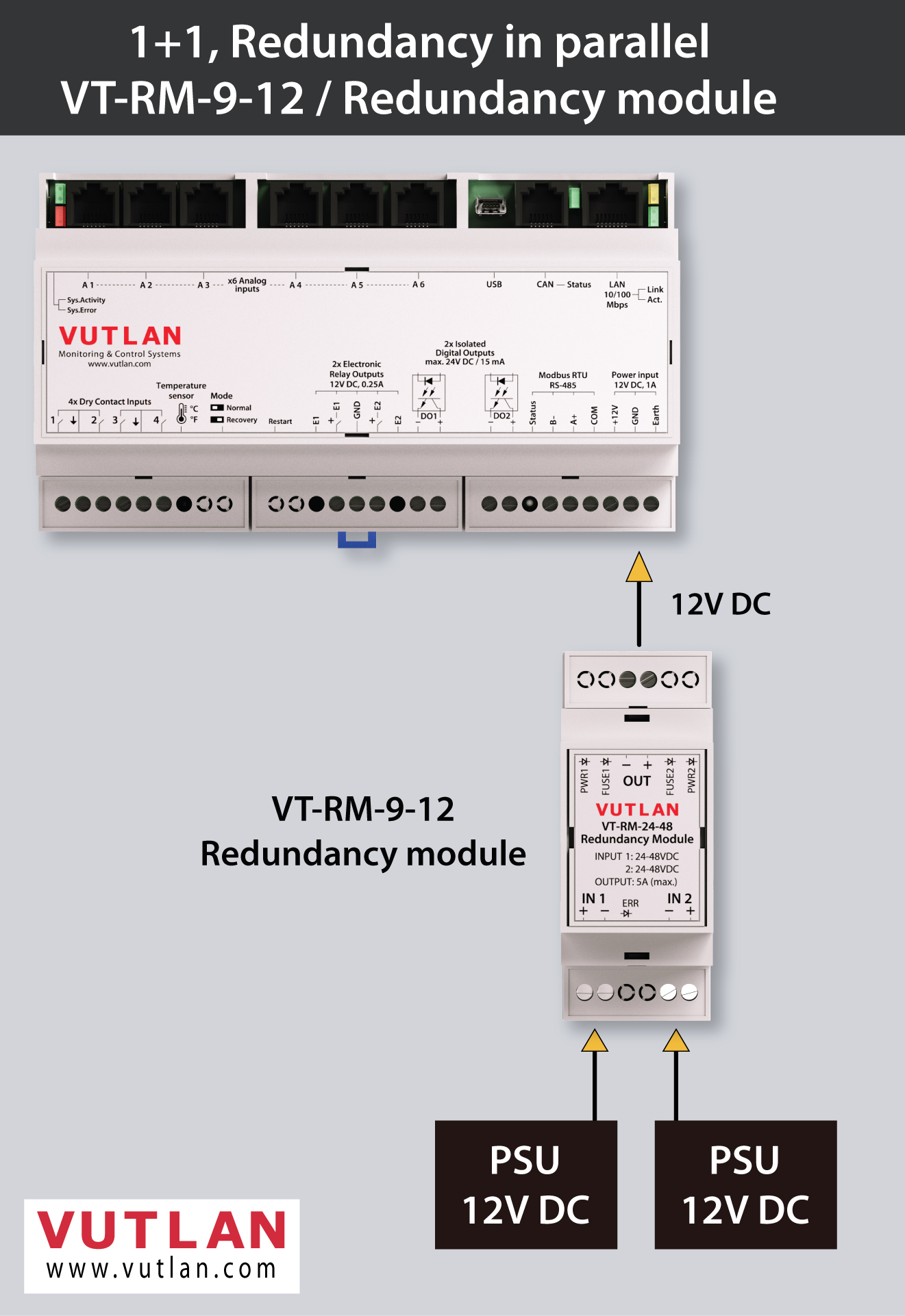
Powering the device using VT-RM-9-12 / Mosfet Redundancy module
VT-RM-9-12 decouples the outputs of the power supplies (9-12VDC, Max. 5A). Automatically supplies load current (Smooth Switchover) from the system input supply with the higher voltage.
Inventory
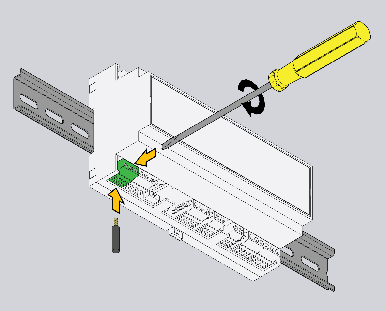
Mounting the device on a DIN rail
| 1 | 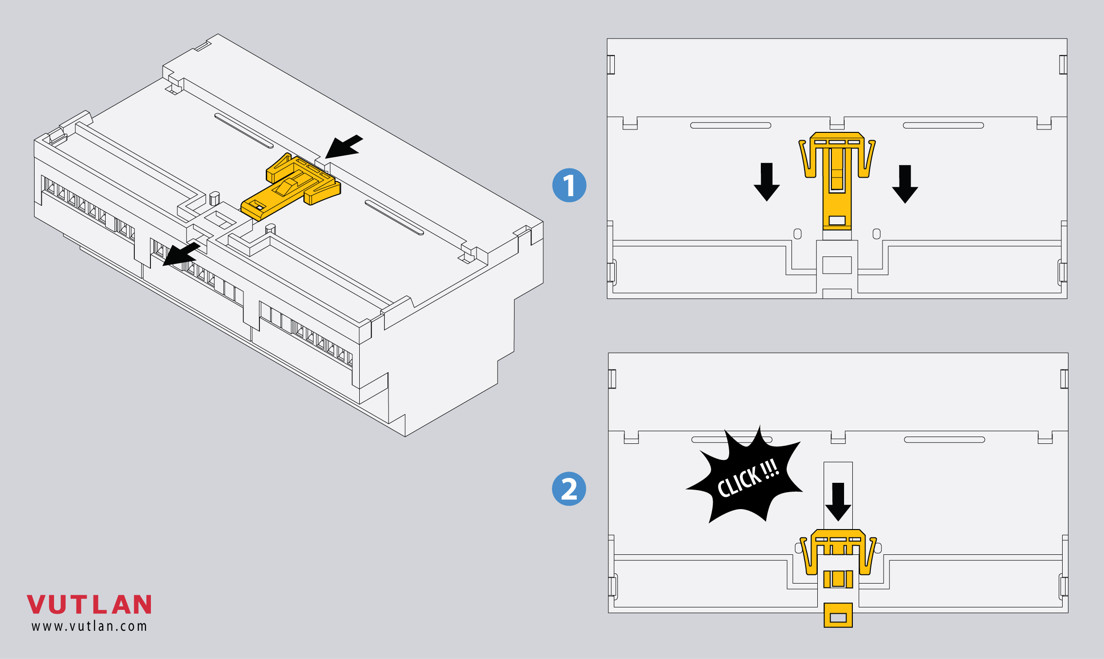 | Insert the DIN rail holder as shown in the picture |
| 2 | 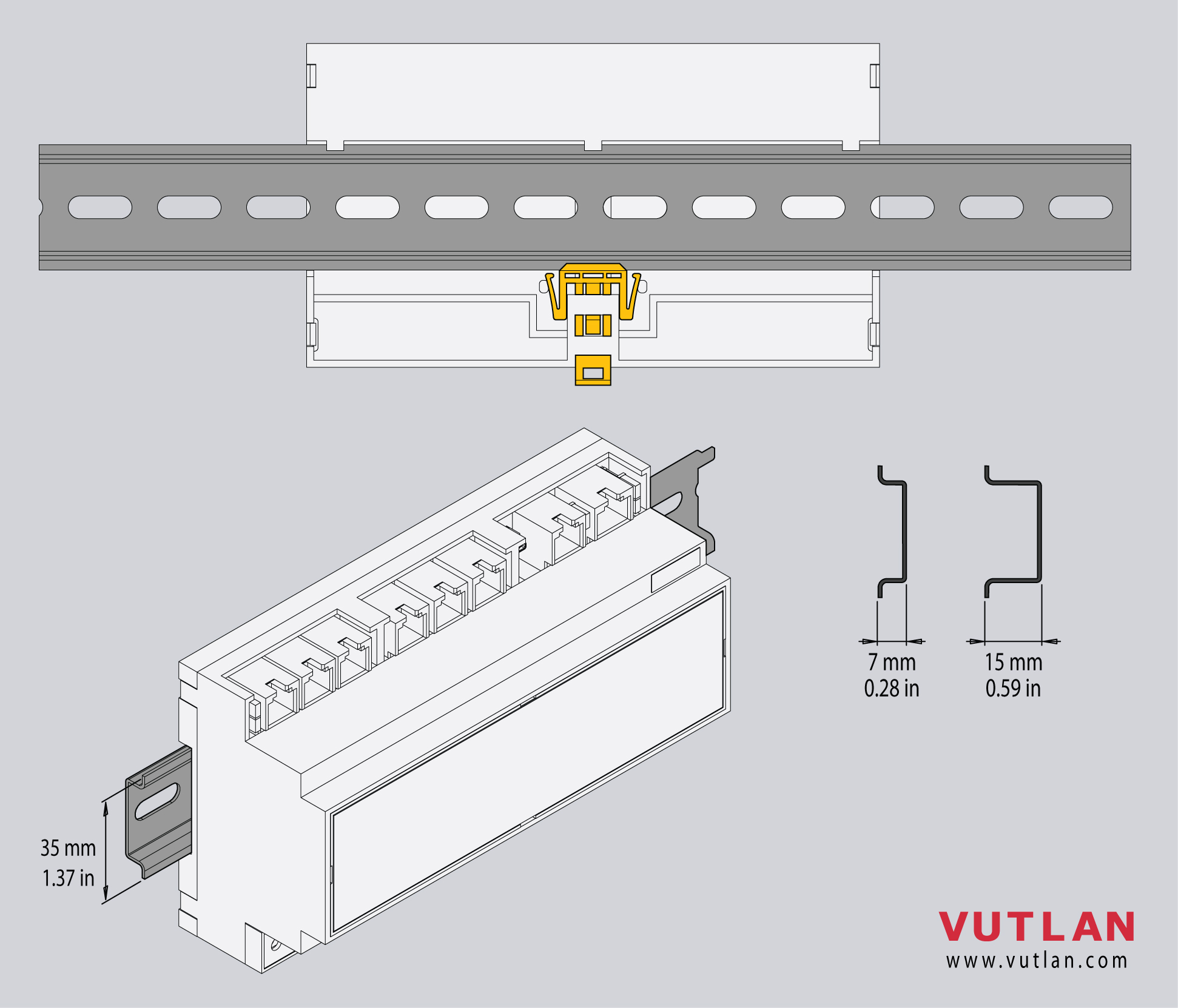 | Press the module onto the DIN rail, it should snap. |
| 3 | 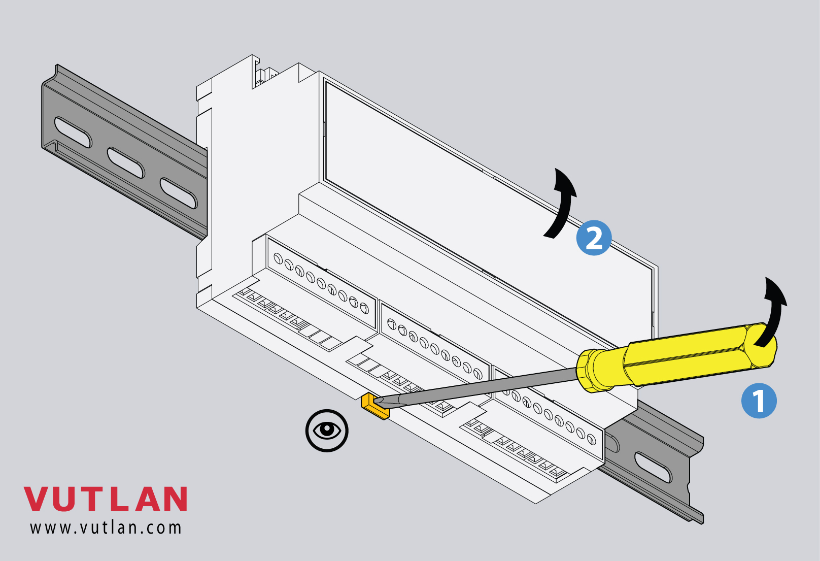 | To dismantle the unit from the DIN rail:
|
Mounting enclosure guards
| 1 |
|
|
| 2 | 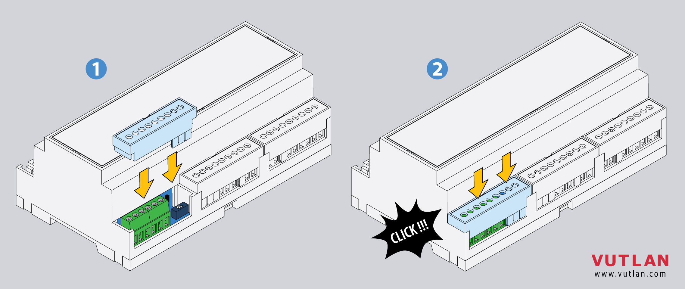 | Simply slide it inside the empty spaces until it clicks. |
| 3 | 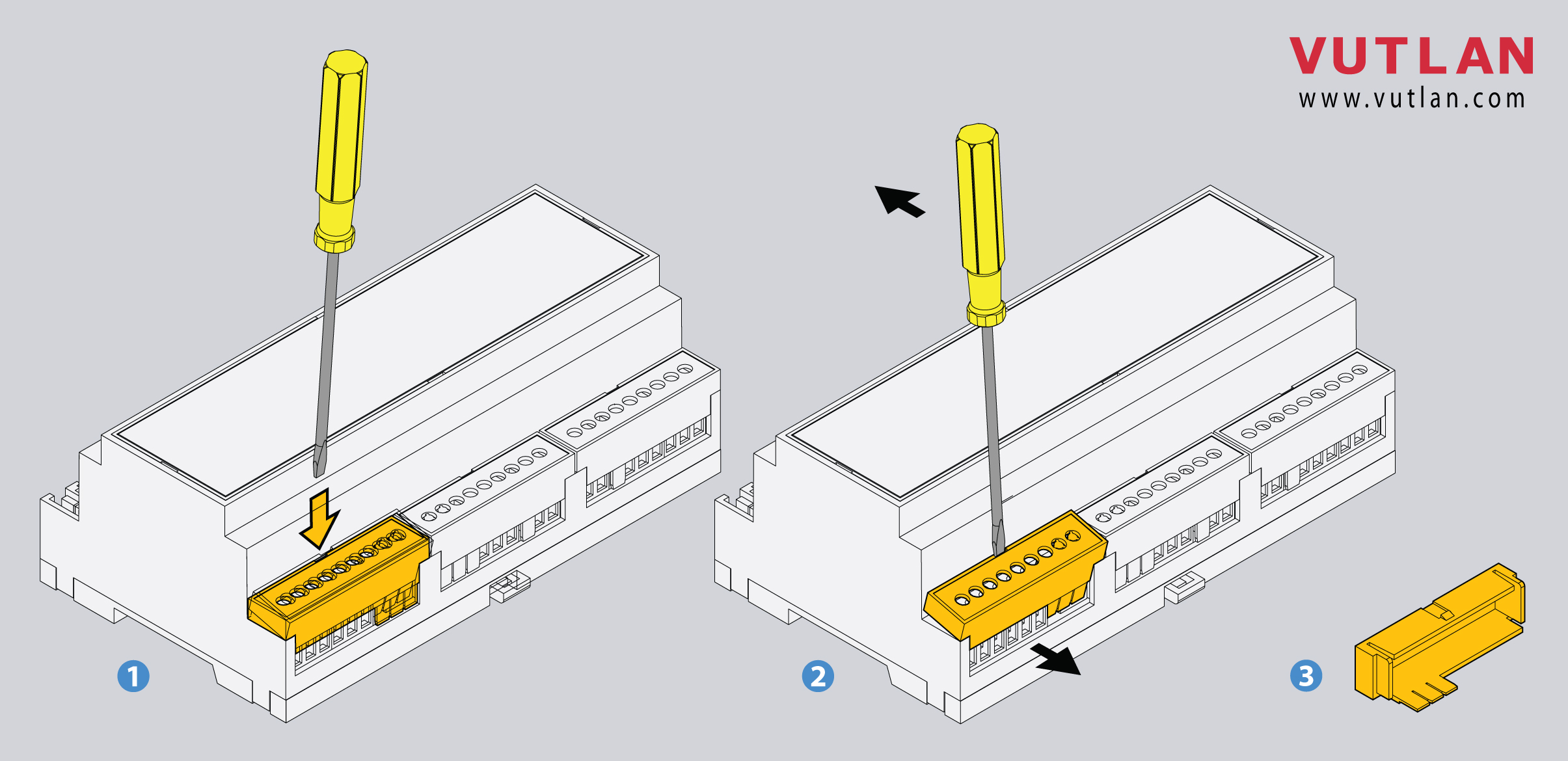 | Use a screwdriver to pull it out. |
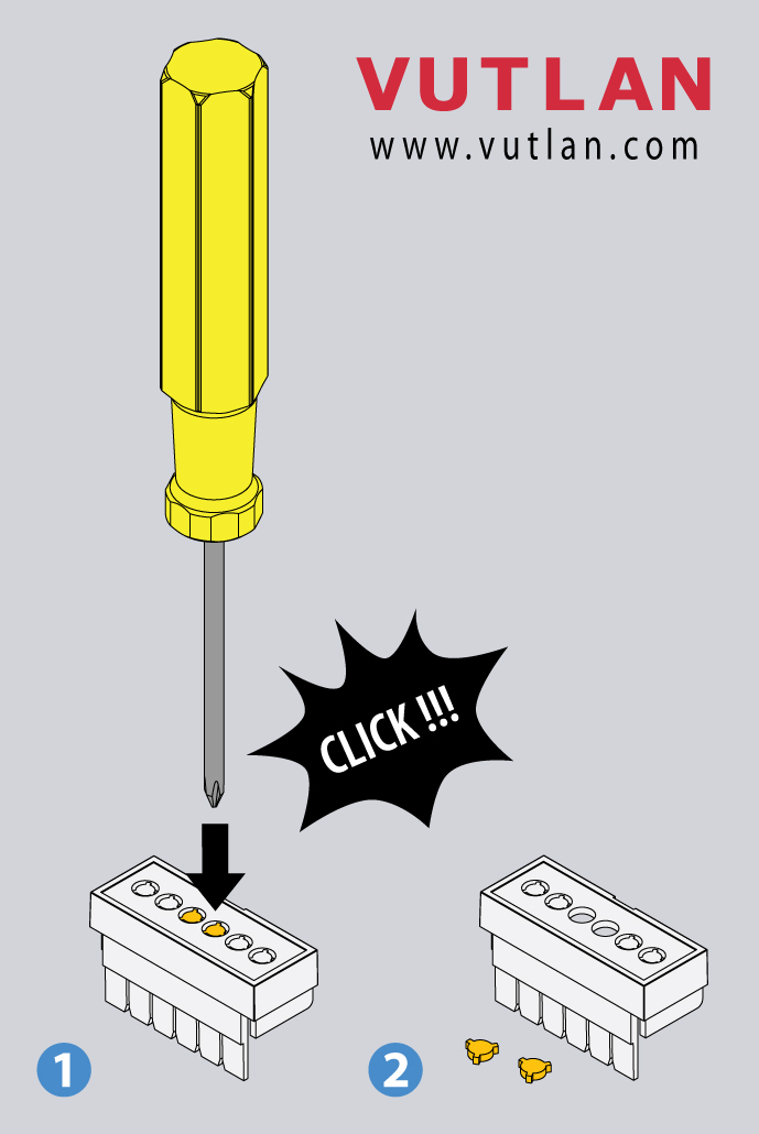
The system uses terminal blocks for several interfaces:
x4 dry contact inputs
x2 Electronic relay outputs
x2 Isolated digital outputs
RS-485 Modbus RTU
Power supply input
They share the same characteristics.
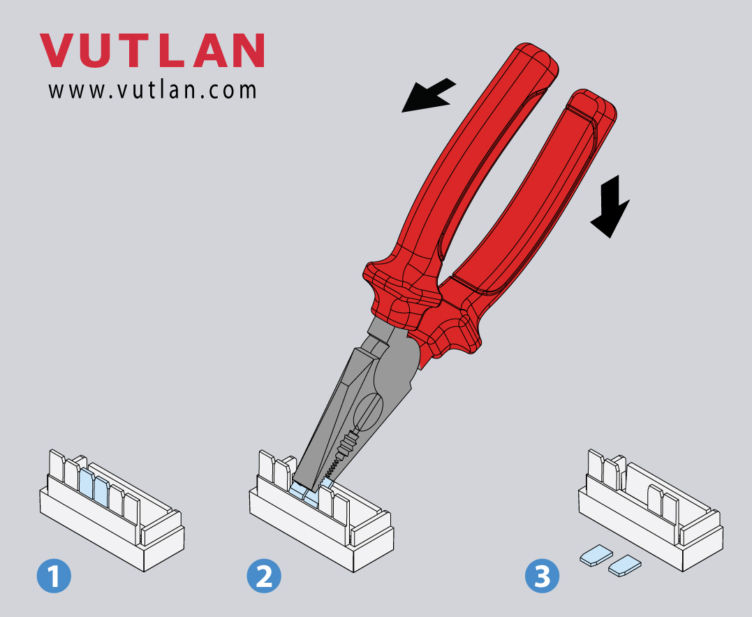
Specifications | Strip length | Wire cross-section | Screw head | |
|---|---|---|---|---|
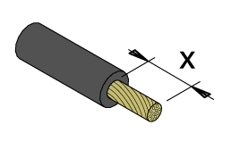 | 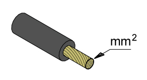 | 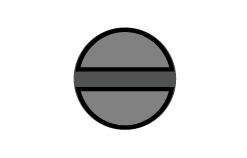 | ||
Terminal blocks Step: 5.08 mm | 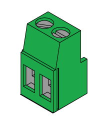 | 6 - 7 mm 0.23 - 0.27 in | 2.5 mm² 0.09 in² #26 - #12 AWG | Flat 3.5 mm 0.13 in |
Using the table above, you can mount the cables.
Device configuration
Developer notes: