Product page: https://vutlan.com/can-sensors/27-vt460-smoke-humidity-and-temperature-sensor.html
Physical description
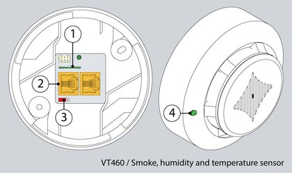
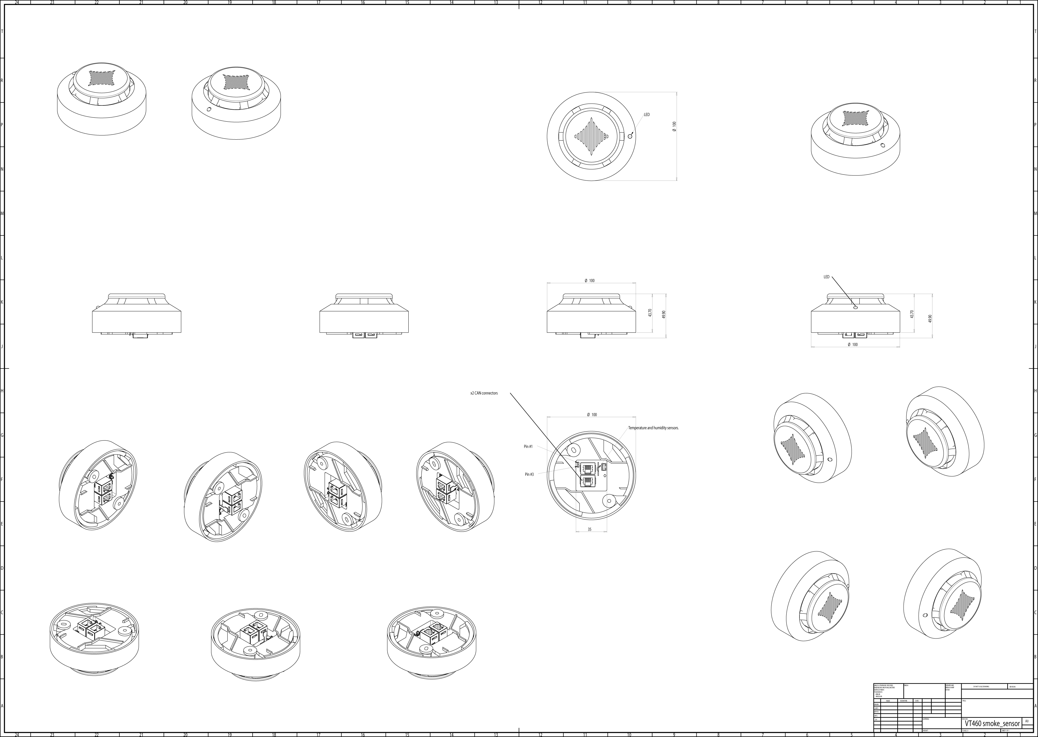
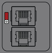
From the picture above:
- Temperature & humidity sensor
- CAN bus ports
- Pinheads (3 pins)
- LED (More info in the "LEDs section" in the article: CAN devices connection)
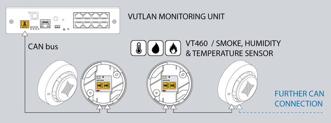
The sensor can not be used on its own. It must be used together with Vutlan monitoring systems.
Installation procedure
Notes on assembly
- It is vital to ensure that the smoke alarm is always assembled with the sensor head pointing downwards. In any other position, there is no guarantee that smoke will be detected.
- The smoke alarm must also be positioned so that it is ventilated with an adequate amount of air and the ventilation slots are not covered.
Installation with the mounting plate provided
The sensor is installed using the mounting plate provided.
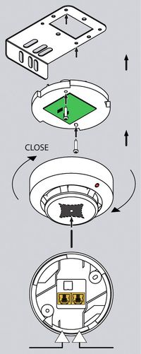
- Uncover the smoke detector head from the base.
- Attach the smoke sensor base to the mounting plate using the M4 x 10 screws provided.
- Replace the sensor head onto the base and secure it by twisting it until it locks home.
- Secure the mounting plate to the enclosure frame using the 4.8 x 19 screws.
- Remove the red protective cap!
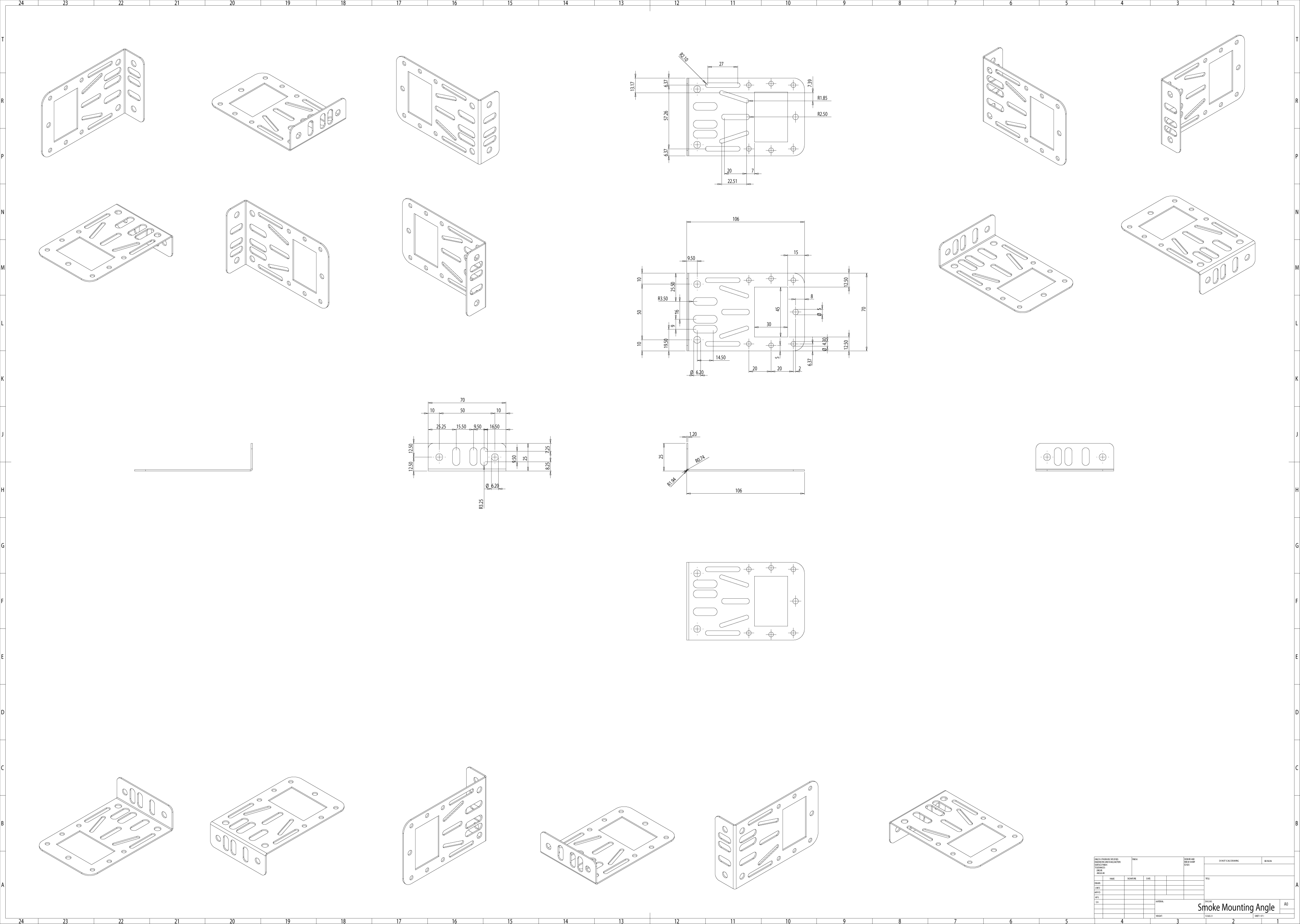
Drawings
Connecting sensor
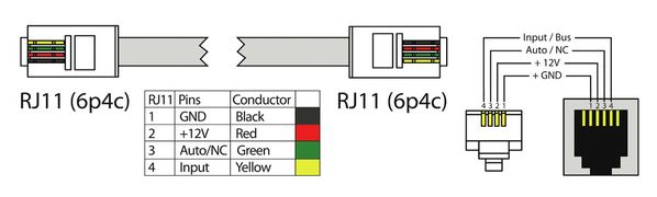
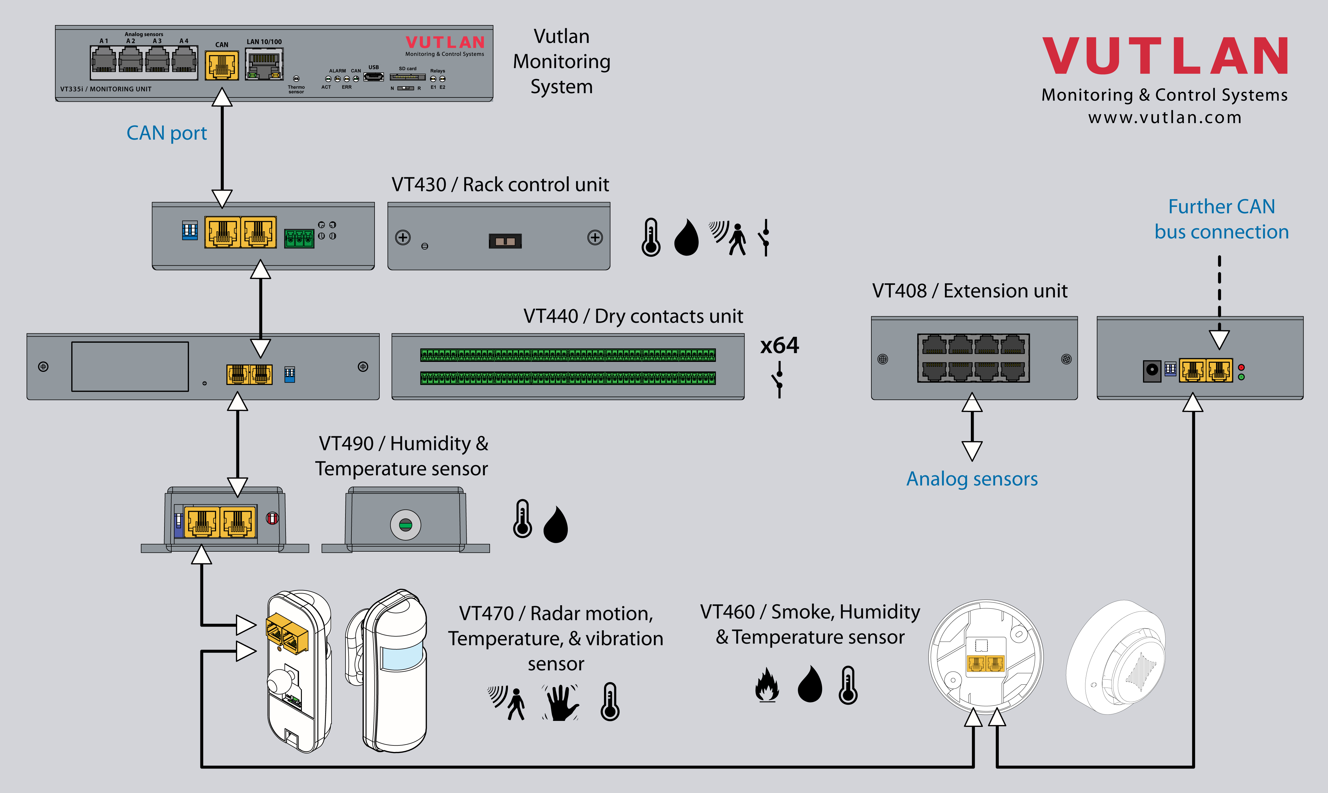
Connect one end of the RJ11 / RJ12 cable to the monitoring unit CAN port and the other end to any CAN input of the smoke sensor. It is possible to connect up to 10 sensors to one CAN port. To do so connect a new RJ11 cable to a free input of an already connected smoke sensor and the other end to the next smoke sensor in a chain. See the picture below. RJ11 or RJ12 cable pinouts can be found in the picture below. After the system will start, configure the CAN bus, after configuration, the LED on the smoke detector will blink dimly once a second.
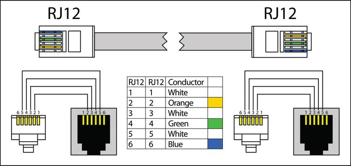
Using the pictures below, install a jumper on VT460.
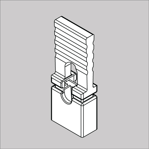
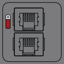
a) For all sensors except the last sensor in the chain put "pinhead jumper" on pins: 2 and 3. TR is OFF.
b) For the last sensor in the chain put "pinhead jumper" on pins: 1 and 2. TR is ON.
Connecting CAN sensors
CAN sensors and CAN units connection
Connect CAN devices to any port CAN1 or CAN2 on the monitoring system using a cable supplied. CAN sensors can also be connected to the port of another CAN sensor or CAN unit that is connected to the CAN bus. Determination of the devices and their connection is done through a web interface.
You can connect up to a maximum of x12 CAN sensors and CAN devices together on one CAN bus (approximately)!
If you want to connect more than x12 CAN units, you need to use CAN-12V-1A / CAN Power Supply
You can connect up to x32 CAN units in a CAN bus chain.
The TR should be "ON" for the last sensor on each bus "CAN 1" and "CAN 2". See section "TR" below.
This procedure applies to the following sensors, which are supported by the appliance and are connected to the CAN ports:
CAN sensors, and modules:
CAN extensions:
Read more about Setting up CAN sensors.
CAN cable and limited line length
The maximum length of the CAN line in Vutlan monitoring systems is 225 m due to limitations on the ohmic resistance of cables with RJ12 connectors.
Vutlan AWG24 cables have low resistance.
Since the conductivity of aluminum is much lower than that of copper, the resistance of CCA cables is much higher than that of pure copper cables of the same size.
It is advisable to use two or three pairs of cables such as UTP Cat3.5.6 with 24AWG with a copper core. It is possible to use a 4-wire or 6-wire TRONIC or UTP CCA cable, but the maximum CAN line length will be reduced.
TR termination switch
The last sensor TR switch on a CAN chain must always be terminated, ( switched ON ). Sensors on a CAN bus that is in the middle should have TR switched OFF.
FR should always be OFF.
TR switch is always the DP switch nearest to the CAN bus.
Only older Vutlan models have an FR switch.
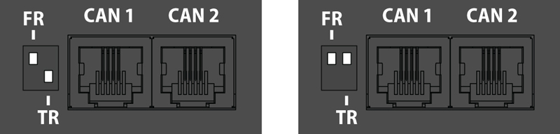
pic.1.1: FR is OFF, TR is ON. pic.1.2: FR is OFF, TR is OFF.
Adding CAN modules and sensors
To connect the CAN module or CAN sensor to the CAN bus of the system, go to the interface >> CAN configuration panel >> Select the CAN1 or CAN2 tab (select the connected physical CAN1 or CAN2 port on the master module).
Click the "Configure" button and wait. The system will start CAN bus polling, soon it will display the data lines and write “Done!”. The modules and sensors connected to the CAN input will appear in a tab in the list. Click the Apply button and then Restart.
The green LED "CAN status" of the device will light up.
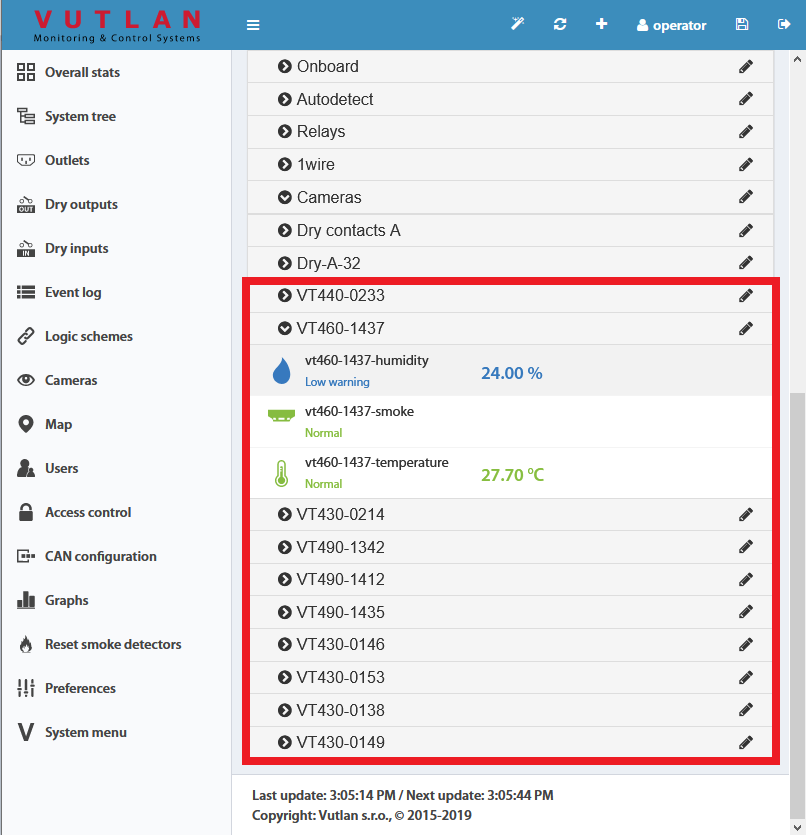
Go to the panel "System Tree" to see the new devices or new sensors. The article numbers for CAN devices are VT4xx. If they do not appear, wait, or refresh.
If after clicking the "Configure" button the poll is reset to the phrase "Update", then the line is not connected or the terminators on the bus are not agreed. It is necessary to check and change the condition of the TR terminators (See "TR termination switch" section above) on the modules or check and possibly change the connection cables.
Warning: If the bus is not matched, that is, there are bad contacts or bad cables, or the TR terminator is in the"ON" position on the intermediate devices (position 2 on the VT408), or the line is too short for matching on both CAN end devices, CAN on this line can work malfunctioning, or the line as a whole may not function. (CAN line failure may occur if the parallel CR switch is in state 1, must be in OFF).
LEDs
CAN sensors have LEDs that indicate the following states:
Red continuous light, green flickers - no communication with the master module
Red continuous light, green is off - there is a connection with the master unit but is not included in the monitoring system (not configured)
Red is off, Green continuously light - work as part of a monitoring system
All LEDs are off: no power or sensor is defective.
Maximum cable length test
Model | Description | 50m | 100m | 150m | 200m |
|---|---|---|---|---|---|
VT408 | Sensor extension unit | ok | |||
VT408DIN | ok | ||||
VT430 | Rack control unit | ok | |||
VT440 | Dry contacts unit | ok | long-chain | ||
VT460 | Smoke, humidity, temperature | ok | |||
VT490 / VT490i | Dual humidity and temperature sensor / Pressure, humidity & temperature sensor | ok |
Additional power for long-chain
When connecting a very long chain, you need to use the CAN-12V-1A / CAN Power Supply module for additional power for CAN units/extensions/sensors every 8-12 sensors.
x2 CAN port systems
Some Vutlan main monitoring systems have x2 CAN ports. That means they can support two individual CAN chains. Each chain has to be configured individually. E.g. “VT855t / Data center monitoring unit” has x2 CAN ports.
Additional reading
see also:
- Comparison chart: Extension units, CAN devices, Sensors
- VT408 / Analog sensor extension unit
- VT408DIN / Extension unit
- VT430 / Rack control unit
- VT440 / Dry contacts unit & VT32 / Dry contacts board extension
- VT450 / Pressure, humidity and temperature sensor
- VT490 / Humidity and temperature sensor
- CAN-12V-1A / CAN Power Supply
- VT460 / Smoke, humidity, temperature sensor (v8.1)
see also:
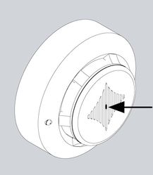
Testing the smoke sensors
During system operation, take a needle or paper clip and insert it into the hole on the cover of the sensor, try to move it there until the blinking dimly LED will flash brightly. That means that sensor is in a good state. After inspection, return the sensor /s to a normal state. To do this, either disconnect them from the system, or in a system interface, go to the smoke sensors tab, and restart them.
False alarms
Avoid high-frequency noise and the impact of dust on the sensor, the noise and dust cause false alarms.
Technical specifications
VT460 | |
|---|---|
| Dimensions | Ø100×45 mm |
| Weight | 290 g |
| Inputs | 2 x RJ-12 |
| Operating temperature | Min. -10° C, Max.80° C |
| Operating humidity | Min. 5% - Max. 95% (Non-Condensing) |
| Power consumption | 100 mW |
| Status Indicators | Red LED |
| Max. distance m | 225 m |
| HS Code | 8531 10 950 |
| Components | Manufactured in E.U. |
| Special Features | Daisy chain |
| Mounting | On the сeiling |
Safety instructions
- Please observe the valid regulations for installation in the country in which the smoke alarm is installed and operated, and the national regulations for accident prevention. Please also observe any internal company regulations, such as work, operating, and safety regulations.
- The technical specifications and limit values stated must not be exceeded under any circumstances. In particular, this applies to the specified ambient temperature range and IP protection category.
- If a higher IP protection category is required for a special application, the smoke alarm must be installed in an appropriate housing or an appropriate enclosure with the required IP protection category.
Configuring CAN sensors
Enable CAN
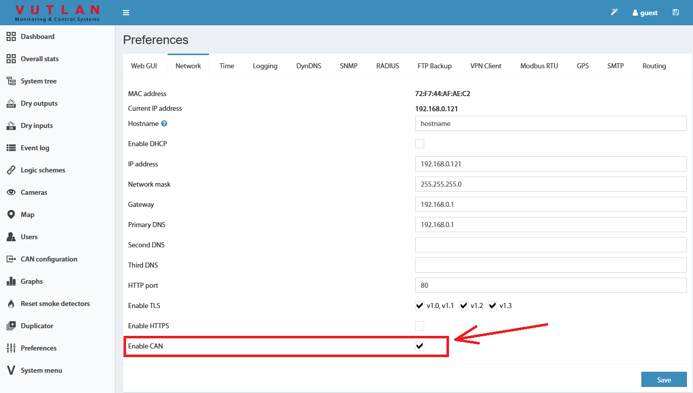
Inside the web interface of the system go to >> Preferences menu >> Network tab >> Enable CAN >> Save >> Save settings to flash (An icon in the top right corner of the web interface)
Configuration
CAN bus is used for the connection of CAN sensors and CAN modules.
Before using the CAN sensor module, the CAN bus must be configured to operate with this CAN sensor module.
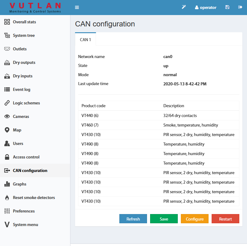
To configure the CAN bus go to "Main menu" >> "CAN configuration" menu.
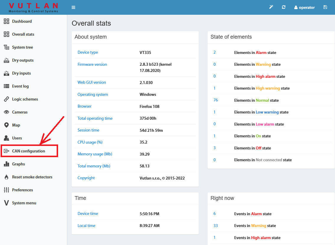
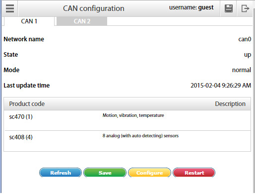
Each station tab contains current information on the status of the node and a list of CAN sensor modules connected to this node.
The following operations can be carried out on the CAN bus node:
Refresh - updates the current information on the status of the node;
Configure - launches configuration process of the nodes for CAN sensor modules connected to it, the old configuration is lost
Save - saves the list of CAN sensor modules in flash memory;
Restart - Restart the CAN bus node.
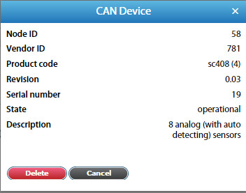
To delete a CAN sensor module, click on the desired module. A modal window will pop up. Press "Delete" and confirm.
To set up a CAN bus node for operation with the CAN sensor module, connect the CAN module to the CAN network and run the corresponding configuration procedure in the web interface using the command "Configure". The configuration process is displayed at the bottom of the tab and lasts approx. 2 minutes. Detected modules will be added to the list of modules during the configuration process. After completing configuration the node returns to its normal operation. Sensors of detected CAN modules are added to the tree of elements.
The names of the sensors are automatically set in the form {module name}{serial number}-{type of sensor} and can be edited.
If you need to remove the CAN sensor module from the configuration list use the command Delete, then use the command "Save" to apply the changes you made and restart the node using the command Restart.
Configuring VT408
The extension unit has built-in elements:
Power - relay type element
This element is identical to the element Analog Power of monitoring units. It turns on or off the power of analog sensors. Turning off the power of analog sensors for a few seconds is used to reset the alarm smoke detectors VT560 connected to the extension unit VT408.
Warning: when the power of analog sensors is OFF, all connected to the VT408 external sensors are OFF.
The settings of analog sensors connected to the VT408 unit are similar to the settings of sensors connected to the monitoring unit.
Additional reading
Copyright:
Vutlan s.r.o.
Remote Infrastructure Monitoring and Control
43 ul.Svornosti, 821 06 Bratislava,
Slovak Republic, E.U.