Using dry contacts can connect the door sensor, window sensor, or other contacts to the monitoring units. Dry contacts have two types: Inputs and Outputs.
Keywords: alarm inputs, digital inputs, dry contact inputs, dry inputs
Dry Contact Inputs (also known as "Alarm inputs", and "Digital inputs")
The inputs of the dry contact must be connected to the outputs of the relay, Opto-relay, button, or switch. It is not allowed to apply any voltage to the dry contact input.
Only a button/relay/switch is connected to the dry contact inputs.
No signals or input voltage can be applied.
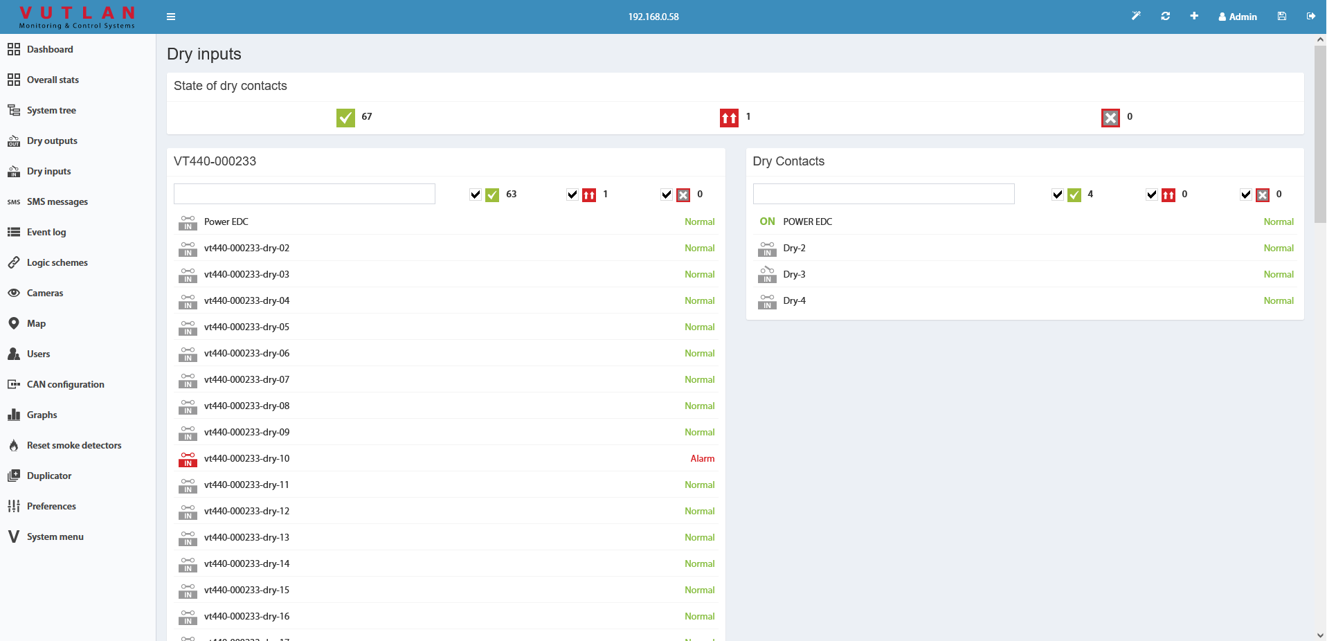
Contacts can be controlled inside the "Dry Contacts / Dry Inputs" panel of the Web Interface of the monitoring unit. The initial state can be configured.
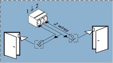
Connection
Connect the wires from the contacts to the corresponding terminals of the connector, each two contacts have a common ground. Plug the terminal into the contact socket. After connecting, configure the trigger logic in the system interface.
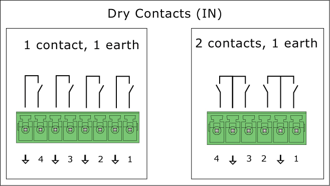
Vutlan monitoring systems may have different types of dry contact inputs:
a) 1 contact and 1 earth
b) 2 contacts and 1 earth
To avoid damage, do not connect the load when the monitoring unit is ON.
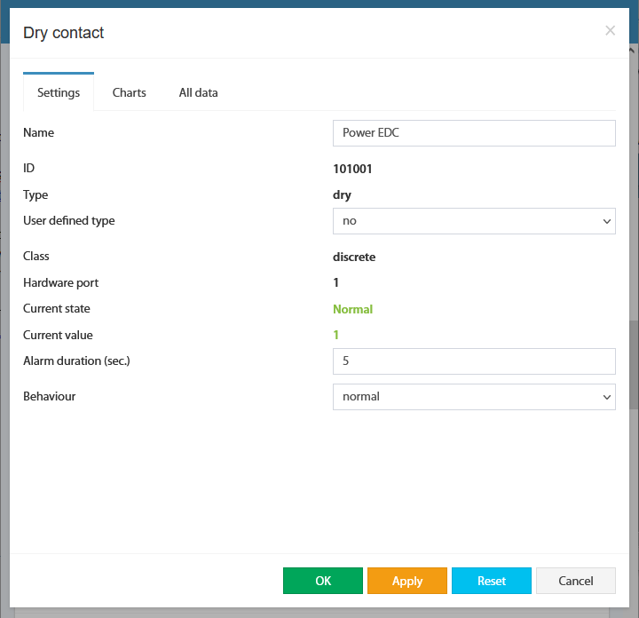
Dry contact settings
Link to the included page: Dry contacts settings
Other pages of interest include: "Connecting dry contacts inputs".
For internal contacts, you can specify the type of behavior (normal or reversive) and specify the type of input. "User-defined type" only affects the icon in the interface. Types can be the following: airflow, door, motion, smoke, vibration, water, and no special type (by default).
For dry contacts on the CAN bus, "Alarm" duration control is also available. This holds on an active level when the signal is already removed from the input. This allows you to suppress the instability of the input signal, if necessary.
The dry contacts window is designed to control dry contacts of internal dry inputs, VT440, VT16, and other extensions. The general view is shown here:
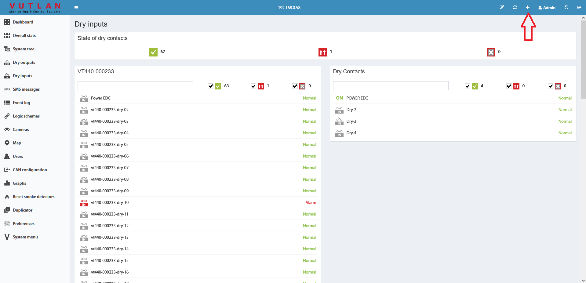
To create the logic for an arbitrary group of contacts press the button " " in the upper left corner. This starts with a wizard creating a logic circuit.
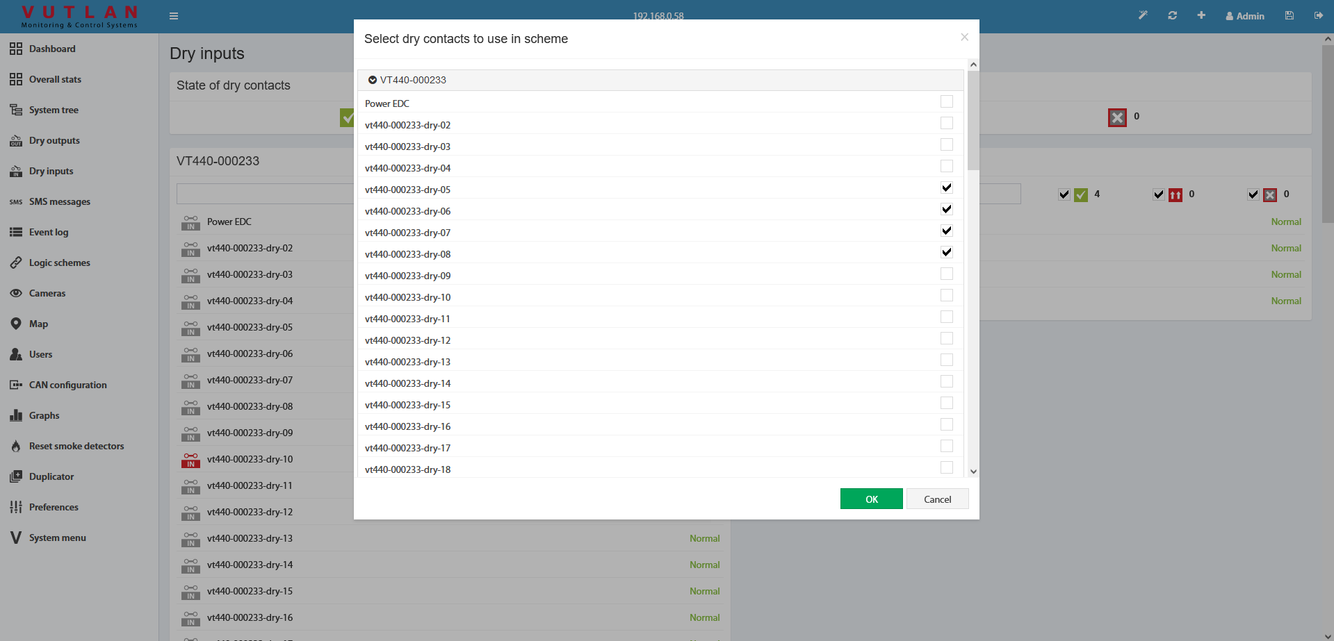
As the first step of the wizard, you must select the dry contacts to create a logical scheme.
After you click OK, you are prompted to create a trigger.
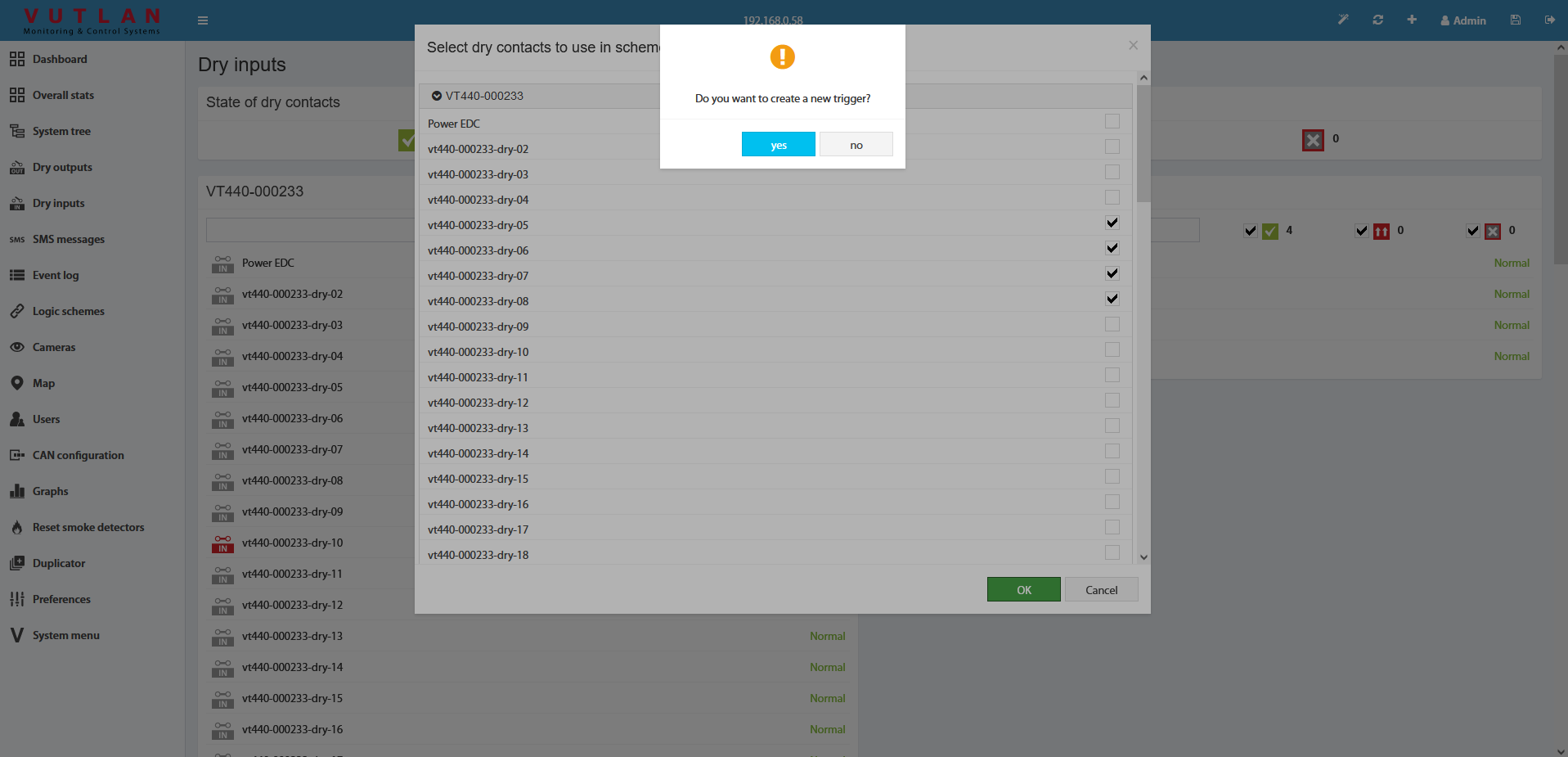
The trigger can be not created. But in this case, in "THEN" the logic circuit can be used only existing elements.
As the last step, you need to edit and create a logic circuit with the OK button.

Do not forget to save all new settings and logic schemes into flash memory by clicking " " in the right top corner of the interface!
Frequently asked questions
Question | Answer |
|---|---|
What is the effective “max” distance that could be realistically supported to monitor Dry contacts? | Very long distances. Two kilometers are easily supported. |
|
|
Copyright:
Vutlan s.r.o. (LLC)
Remote Infrastructure Monitoring and Control
43 ul.Svornosti, 821 06 Bratislava,
Slovak Republic