...
2. "Analog sensors: A1..A6" - x6 RJ12 analog sensor inputs with auto-sensing. Read instructions at "Analog sensors connection", and "Sensor configuration".
3. "USB" - type miniAB USB-port 2.0, required to connect a USB camera, USB flash, USB hub or to restore an appliance using USB flash.
4. "CAN" - digital connector RJ12 for the connection of CAN sensors and CAN extensions on a CAN bus, with auto-sensing. Read the instructions at in "CAN devices connection", and "Setting up CAN".
"CAN Status" - LED for digital bus sensors:
...
6. "DRY CONTACT INPUTS 1...4" - Digital inputs. Read the instructions at "Connecting dry contacts inputs", and "Dry contacts settings".
7. "TEMPERATURE SENSOR" - accuracy +/- 1 °C.
...
Normal mode 🠀: Normal operating state. The system should always be always switched to this.
Recovery 🠂: Turns a recovery mode On. Use this option only in case you need to recover manufacturing settings. Read instructions at "Factory settings recovery".
...
10. "OUTPUT 12V 0.25A" - 12V 0.25A output electronic relay terminal. Read the instructions at "Connecting 12V devices to 12V outputs".
11. "ISOLATED DRY CONTACTS OUTPUTS 1...4" - Digital outputs 24VDC / 15mA (type OUT). Read the instructions at "Connecting dry contacts inputs", and "Dry contacts settings".
12. "RS-485 MODBUS RTU" - port for connecting Modbus RTU / RS-485 sensors and devices. Read instructions at "Connecting Modbus RTU sensors to VT336 & VT336PoE", and "Configuring Modbus devices".
...
14. "Modem" - "VT770 / LTE, GPS modem" is ordered separately. Read instructions at "Connecting VT770 / LTE modem with GNSS", and "Networking".
"Modem status" - LED displays modems modem status.
"SIM card slot" - Open the top cover to insert a SIM card.
"GSM, LTE main antenna" - Connect GSM or LTE main antenna.
"LTE auxiliary antenna" - Connect LTE auxiliary antenna (Auxiliary LTE antenna and antenna output are ordered separately from the modem). It helps to establish a stronger and more stable signal.
"GPS active antenna" - GPS antenna and antenna output are ordered separately from the modem. Allows It allows one to set the time using GPS and shows the location of the device on the map.
...
Product info is located on the product page "VT336 product page".
Powering the device
...
Power supply with grounding.
Power supply without grounding.
...
Inventory
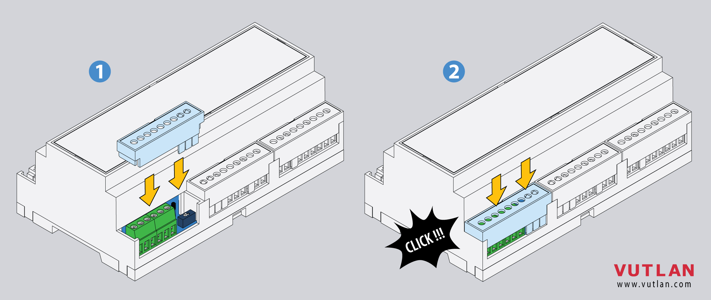
Mounting the device on a DIN rail
1 |
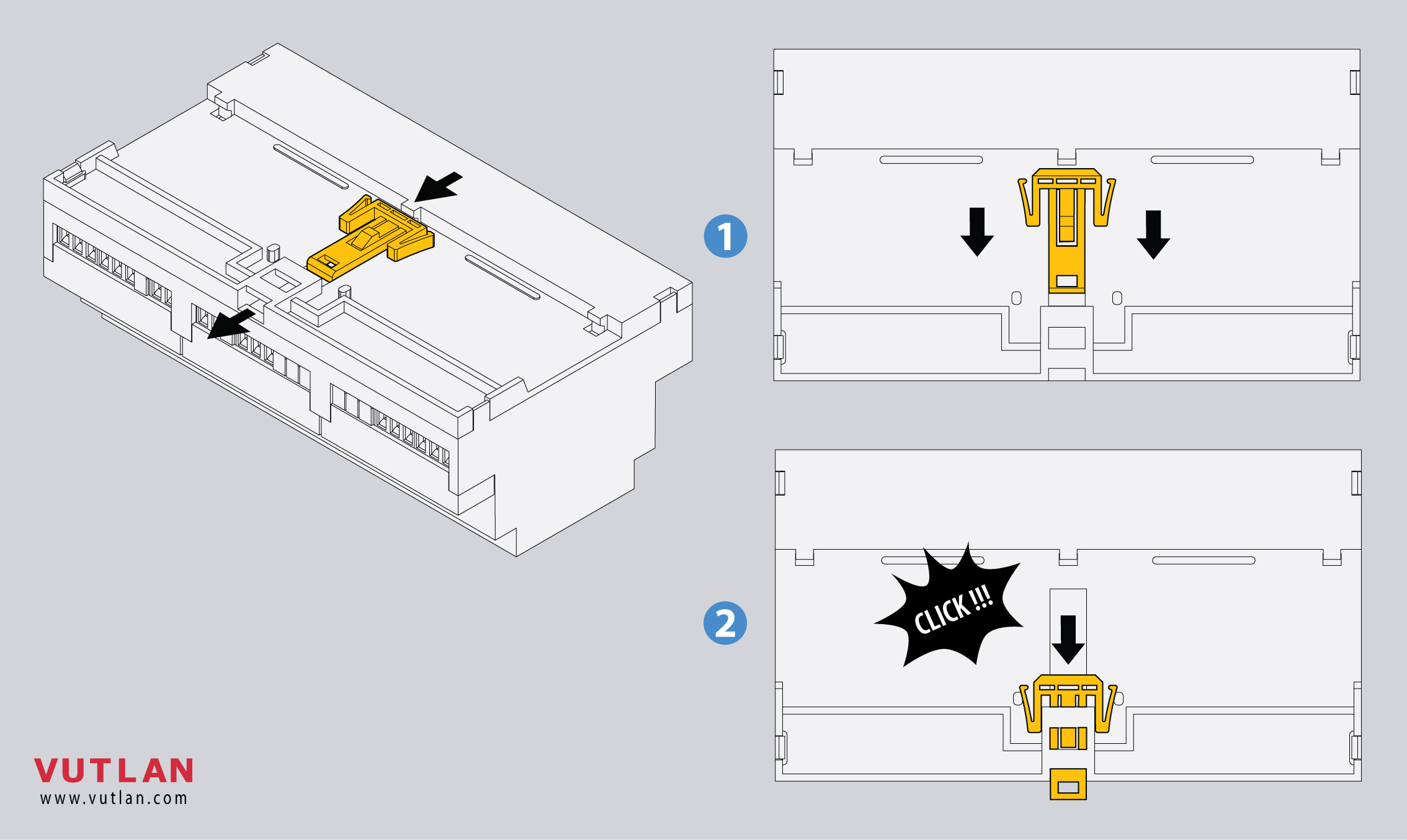
 | Insert the DIN rail holder as shown in the picture |
2 |

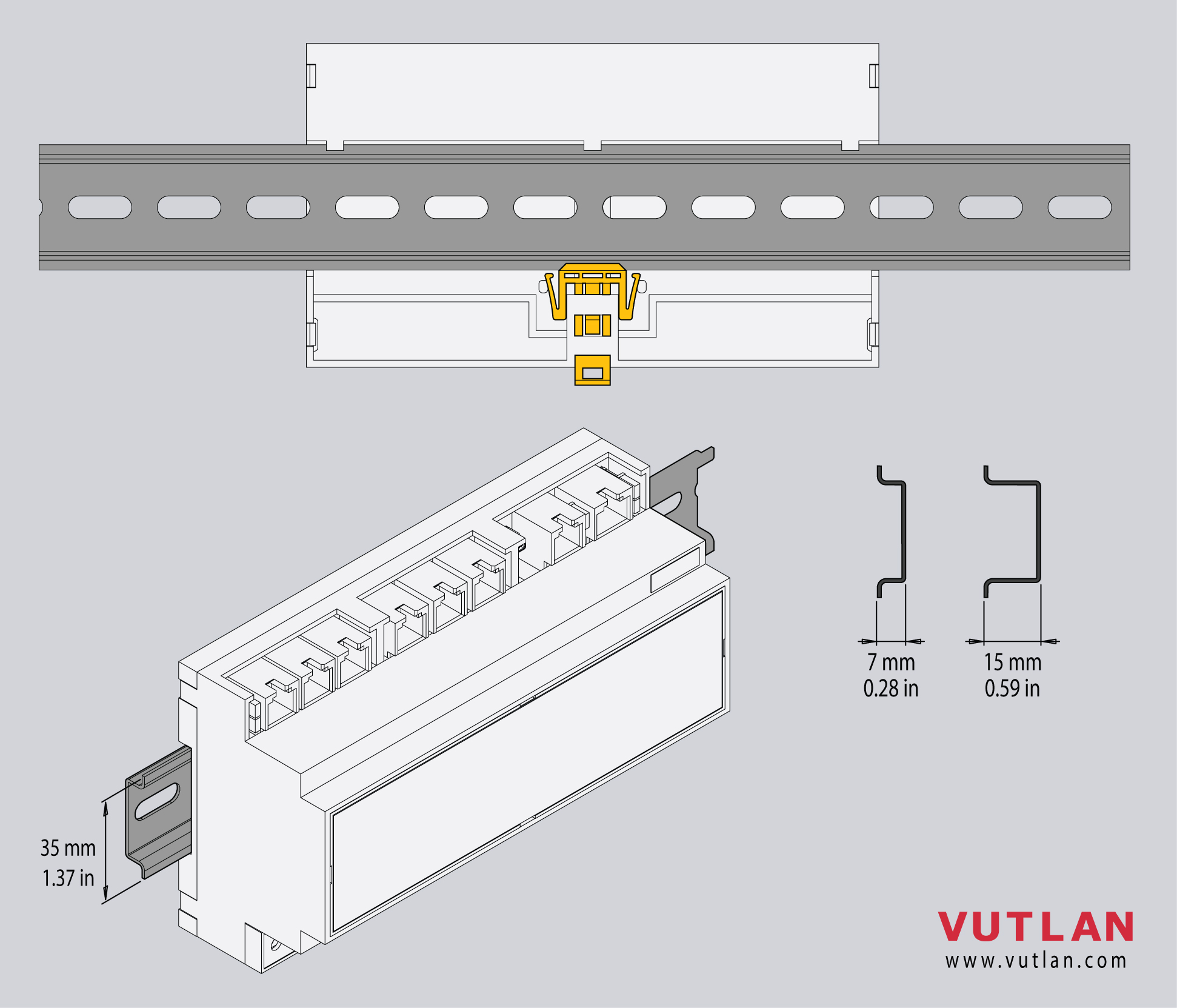 | Press the module onto the DIN rail, it should snap. |
3 |

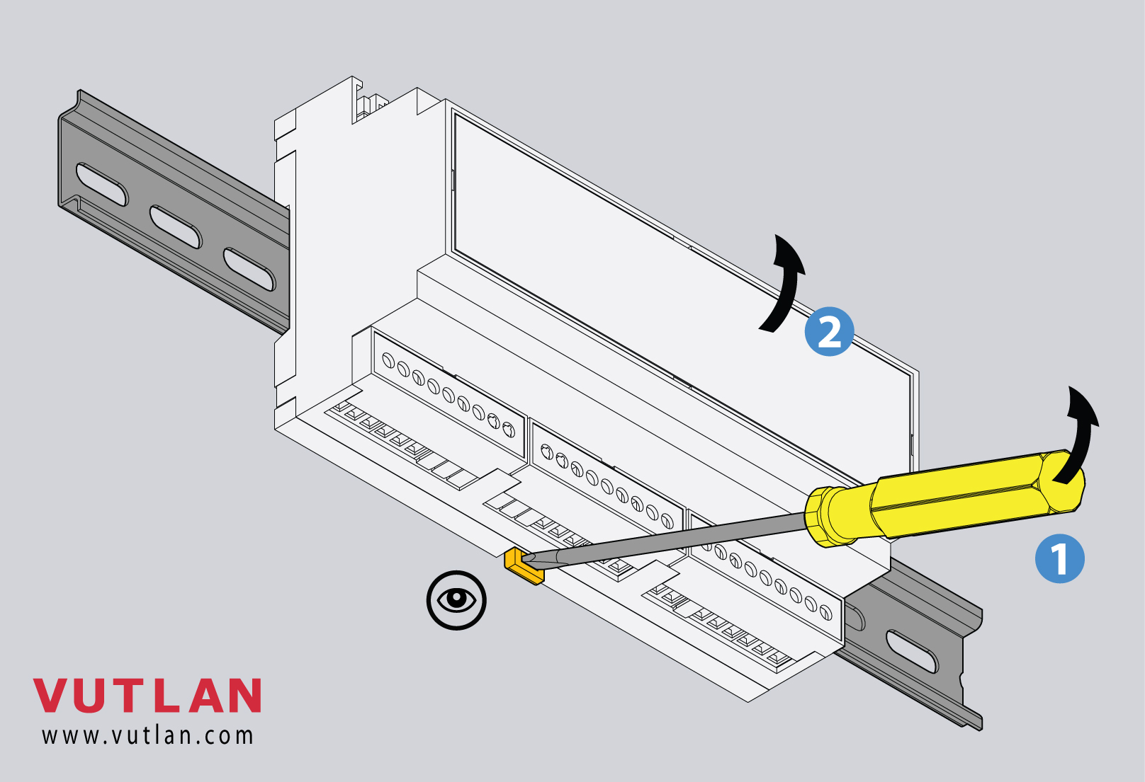 | To dismantle the unit from the DIN rail:
|
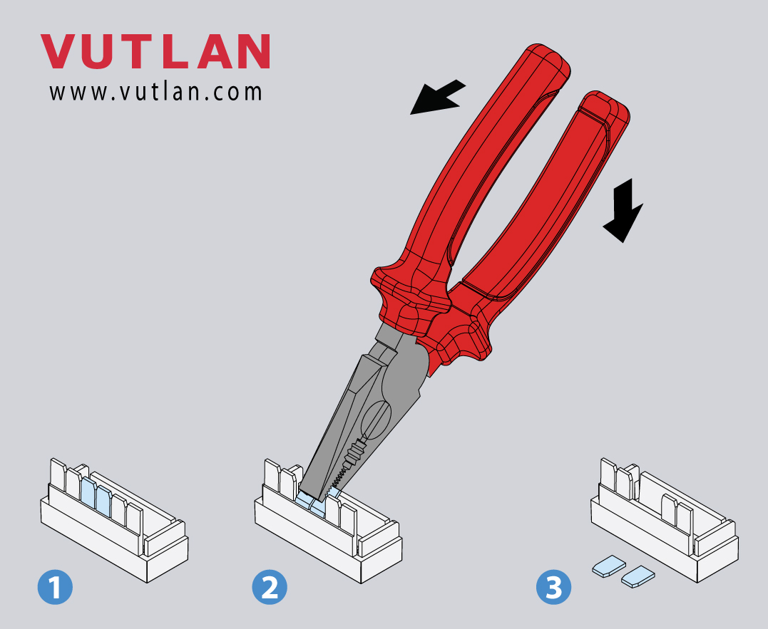
Mounting enclosure guards
1 |
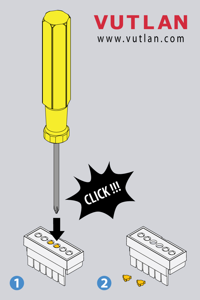
  |
|
2 |

 | Simply slide it inside the empty spaces until it clicks. |
3 |
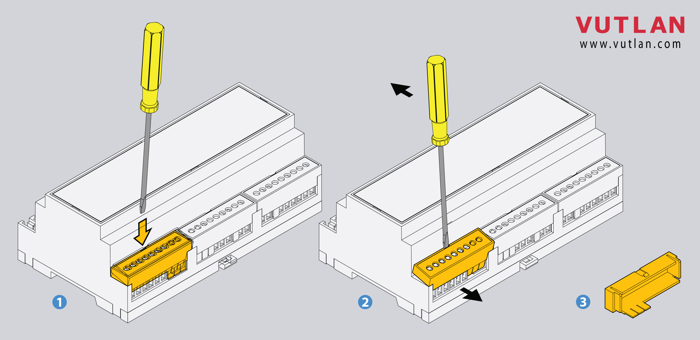
 | Use a screwdriver to pull it out. |
| Include Page | ||||
|---|---|---|---|---|
|
...
...