Physical description
When "VT10" is installed inside of monitoring unit, "VT10" looks like this:
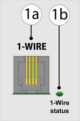
1a. RJ9 jack for connecting 1-Wire sensors.
1b. Green LED. If the green light is "ON", then 1-Wire board is on. There's an element inside monitoring unit's interface that can be switched "ON" and "OFF", which activates 1-Wire bus.
Connection
Monitoring units have the option of installing "VT10 / 1-Wire board" (expansion board). The board is mounted and connected inside the monitoring unit. 1-Wire technology is based on a serial communication protocol that uses one data line and a reference ground between the master (for example, the VT335 / Monitoring Unit) and one wire slave.
Installation and connecting of VT10 1-Wire board
To install and to connect extension units: switch off appliance, unplug from the outlet or disconnect the power connector.
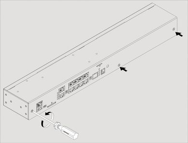
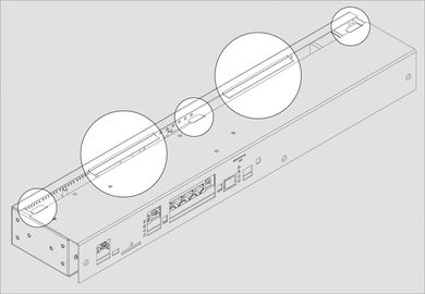
| 1 | Carefully unscrew screws holding the cover and open it. Depending on the monitoring system, it may have: 1-Wire, Antenna, GSM or Dry Contacts or any other additional modules installed inside. Carefully open the box by unplugging, if necessary, any cables that connect from top cover to bottom cover. | |
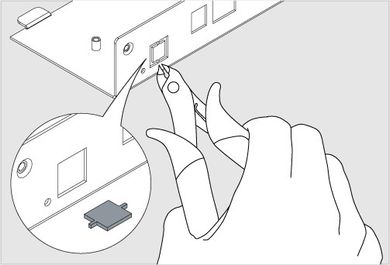
| 2 | Break 2 steel bridges in the 1-Wire hole of the appliance case (e.g. VT335 top metal)cover. Using forceps (cutter) with thin nozzles cut the thin bridges in the hole. Make sure that no burrs are left. | |
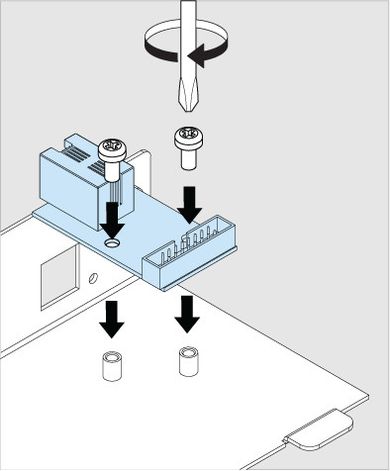
| 3 | Set up 1-Wire board on 2 steel spacing sleeves inside the appliance case (e.g. VT335 top metal cover), attach the board with two M3 screws from supply to the sleeves. | |
| 4 | 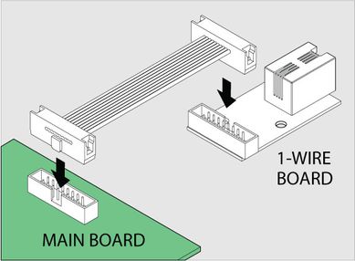 | Connect "16 wire IDC16 flat cable" supplied with "1-Wire extension" board to the connector on the 1-Wire board and on main board (e.g. VT335 board). |
| 6 | Close and fasten the cover. Carefully place top cover back so that all cover wings fit in and all cutoffpoints match the panel holes. |
Activating 1-Wire interface:
After "VT10 / 1-Wire board" has been installed inside the system, You need to check if the 1-Wire interface is On. Instructions can be found here: Setting up 1-Wire
Connecting 1-Wire sensors:
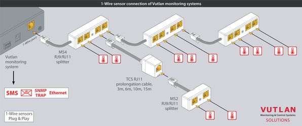
All 1-Wire sensors are Plug&Play. Use following examples for instructions on how to connect sensors:
Example 1:
.jpg?version=1&modificationDate=1526027076108&cacheVersion=1&api=v2&width=645&height=250)
Example 2:
Package includes:
VT10 / 1-Wire Board (Inventory)
Accessories:
You can use a range of accessories for 1-Wire interface. Accessories are ordered separately.