Content
Introduction
Most Vutlan monitoring systems have dry contact input terminals. It allows the system to receive alarm and alert signals (take health and fault status).
You can connect the contact door sensor, window sensor, UPS, diesel generators, circuit breakers, alarm system, control panels, and other industrial equipment.
Keywords: alarm inputs, digital inputs, dry contact inputs, dry inputs, volt-free contacts, UPS monitoring, take fault status, take healthy status,
Dry inputs panel
The “Dry inputs” panel shows all dry input terminals, and dry input extension devices connected to the system. You can configure normal and reverse states, rename elements, set defined types, create groups.
It is possible to add more dry contact inputs by using VT440 / Dry contacts unit & VT32 / Dry contacts board extension CAN extension unit.
Configure
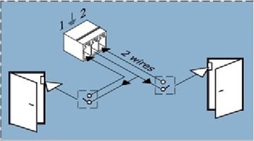
The inputs of the dry contact must be connected to the outputs of the relay, Opto-relay, button, or switch. It is not allowed to apply any voltage to the dry contact input.
Only a button/relay/switch is connected to the dry contact inputs.
No signals or input voltage can be applied.
Contacts can be controlled inside the "Dry Contacts / Dry Inputs" panel of the Web Interface of the monitoring unit. The initial state can be configured.
Connection
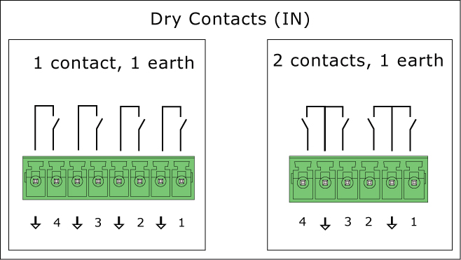
Connect the wires from the contacts to the corresponding terminals of the connector, each two contacts have a common ground. Plug the terminal into the contact socket. After connecting, configure the trigger logic in the system interface.
Vutlan monitoring systems may have different types of dry contact inputs:
a) 1 contact and 1 earth
b) 2 contacts and 1 earth
To avoid damage, do not connect the load when the monitoring unit is ON.
Dry contact settings
Included page Dry contacts settings panel
Link to the included page: Dry contacts settings panel
Other pages of interest
"Connecting dry contacts inputs".
Using Groups
There can be a lot of dry contacts and sometimes you just want one triggered event for many of them at the same time. You can create a group and place multiple dry contacts into it. Any element in the group will trigger an event such as a notification for example.
Introduction
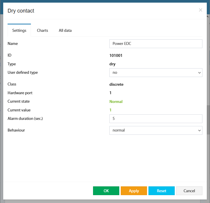
For internal contacts, you can specify the type of behavior (normal or reversive) and specify the type of input. "User-defined type" only affects the icon in the interface. Types can be the following: airflow, door, motion, smoke, vibration, water, and no special type (by default).
For dry contacts on the CAN bus, "Alarm" duration control is also available. This holds on an active level when the signal is already removed from the input. This allows you to suppress the instability of the input signal, if necessary.
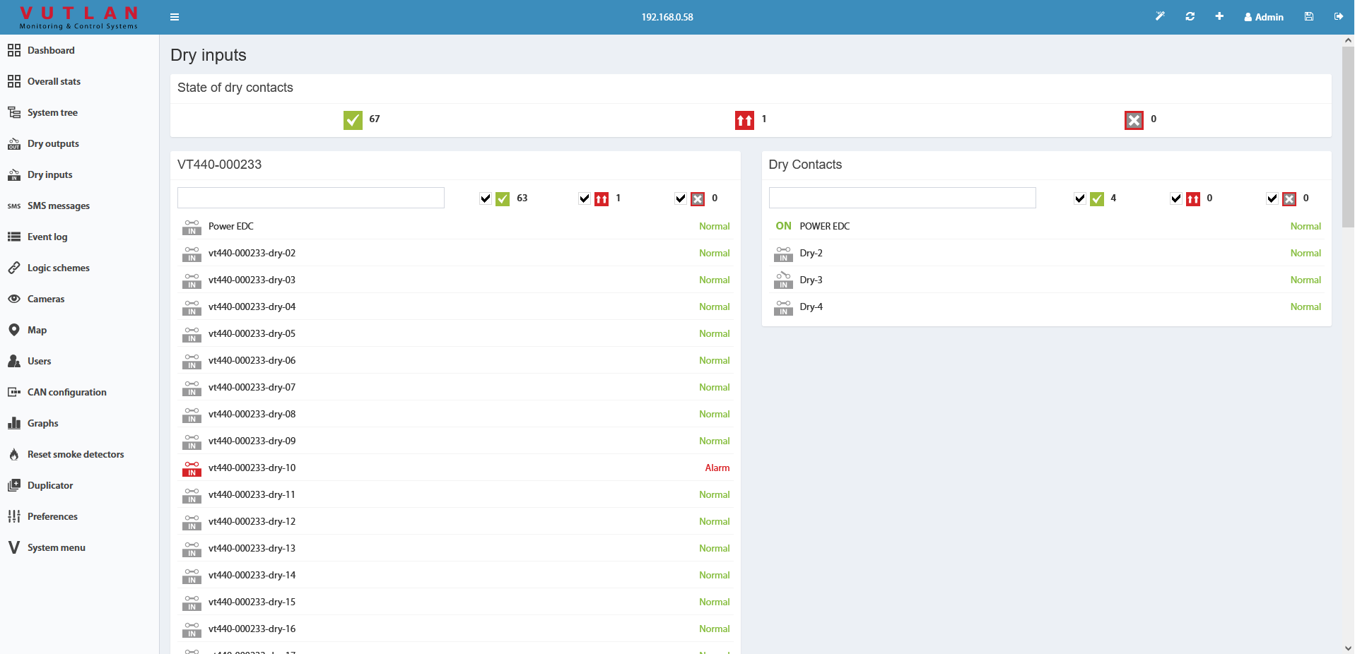
The dry contacts window is designed to control dry contacts of internal dry inputs, VT440, VT16, and other extensions. The general view is shown here:
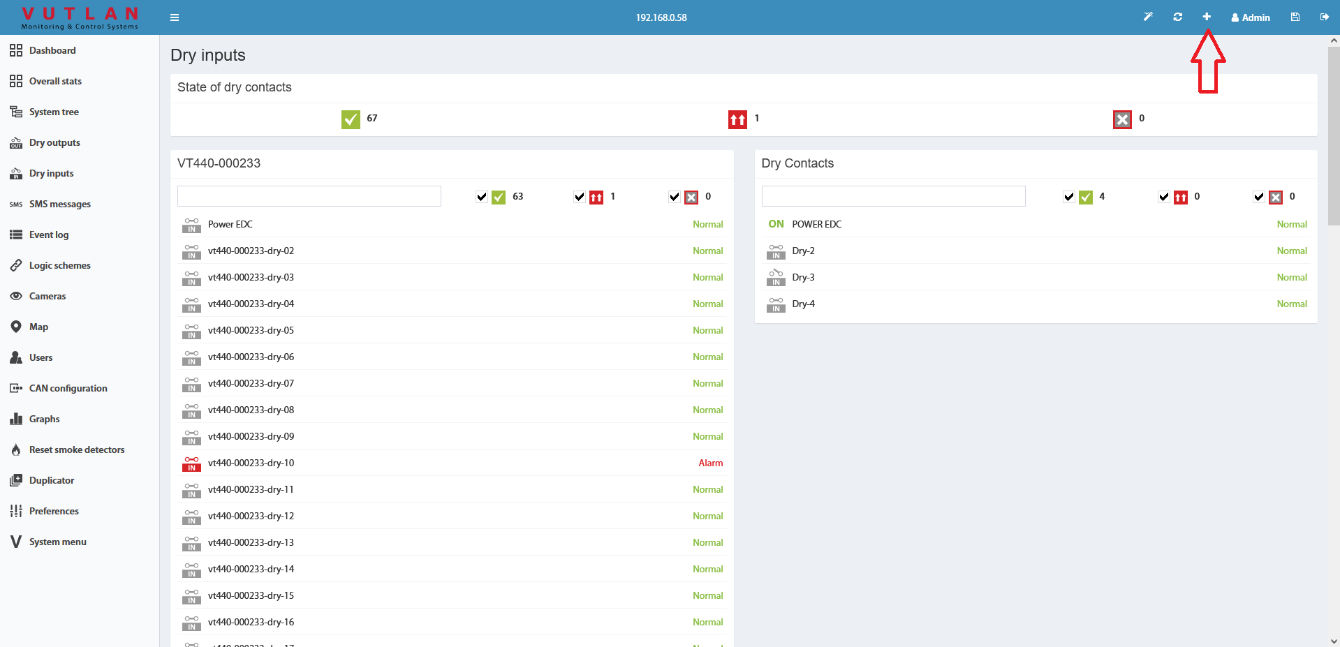
To create the logic for an arbitrary group of contacts press the button "" in the upper left corner. This starts with a wizard creating a logic circuit.
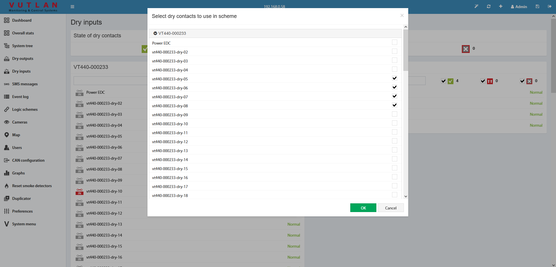
As the first step of the wizard, you must select the dry contacts to create a logical scheme.
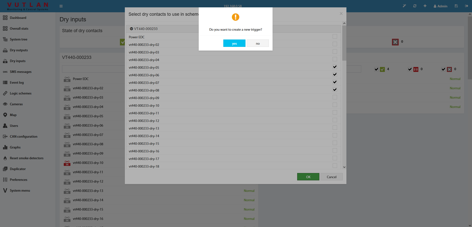
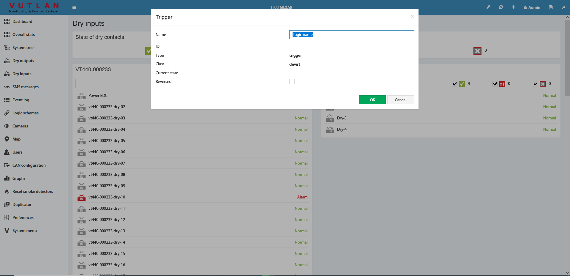
After you click OK, you are prompted to create a trigger.
The trigger can be not created. But in this case, in "THEN" the logic circuit can be used only existing elements.
As the last step, you need to edit and create a logic circuit with the OK button.
Do not forget to save all new settings and logic schemes into flash memory by clicking "" in the right top corner of the interface!
VT440 / Dry contacts extension unit
page linked VT440 / Dry contacts unit & VT32 / Dry contacts board extension
Documentation page: https://vutlan.atlassian.net/wiki/spaces/DEN/pages/35127335/VT440+Dry+contacts+unit
Product page VT440: https://vutlan.com/can-sensors/24-vt440-dry-contacts-unit.html
Product page VT32: https://vutlan.com/contacts/9-vt32-dry-contacts-board.html
Function and purpose
The VT440 extension unit allows for increasing the number of dry contact input terminals connected to any Vutlan monitoring unit. Each VT440 adds 32 dry contacts, providing scalable monitoring capabilities for complex infrastructures. It can be easily connected to any CAN port within a CAN bus chain and can be daisy-chained with other CAN sensors, ensuring seamless integration and flexible system expansion for enhanced monitoring and control.
The number of dry contacts inside VT440 can be increased up to 64 with an extension module "VT32 / dry contacts module".
CAN devices and sensors can be chained together. Up to 10-32 CAN devices can be connected in a chain. You can connect CAN sensors or extensions on a CAN bus line.
Usage
Dry contact usage examples:
General Alarm
System Healthy status
System Common Fault Alarm
Door open/closed
A window opened/closed
HVAC on/off state
Power supply control (controls On/Off state of any connected devices)
Order options
VT440 can be ordered in two options:
a) VT440 (x32 dry contact inputs)
b) VT440 + VT32 (x64 dry contact inputs)
Physical description
1. "1...32" - Dry contacts terminal.
2. "33...64" - Dry contacts empty slot. VT32 / Dry contacts board is ordered separately.
3. "S/N" - serial number. You will need this serial number if you want to contact our support team. You mustn't lose it!
4. LEDs: "RUN" - indicates appliance connection status to the main module, "ERR" - indicates appliance lost connection to the main module.
5. "CAN 1", and "CAN 2" - two equivalent digital connectors RJ12 for the connection to the master module, CAN sensors, or CAN extensions on a CAN bus, with auto-sensing.
6. "TR" - is the nearest switch to CAN inputs. This switch should be turned "ON" on the last sensor in the CAN chain. The last sensor in the long chain with a length of more than 10 meters, the terminator should be in the "OFF" position.
Do not use the DIP switch "FR" labeled "1", it should always be OFF. If this switch is turned ON, the module will turn off. This switch is only needed for programming purposes
Diagram
The following diagram shows how you can connect multiple VT440 units on a CAN bus chain to a main monitoring system.
Technical specifications
Communications | Description |
|---|---|
Type | CAN bus extension |
Network interface | CAN open |
Input terminals | x32 dry contacts inputs terminals (2 wires) x2 RJ11/RJ12 6P4C ports for CAN bus |
Daisy chain | Yes, possible. |
Usage | Adds x32 dry contact inputs (digital inputs) |
Accessories | Description |
Expansions (ordered separately) | "VT32 / Dry contacts board" - adds additional x32 contacts |
Environmental | Description |
Operating temperature | Optimal range: -10° C to +80° C Extended range: -40° С to +100° C |
Storage temperature | -40° С to +100° C |
Operating humidity | 0 to 95 % |
Storage humidity | 0 to 95 % |
Power requirements | Description |
Power Consumption | 1 Watt |
Max. distance from the unit | 225 m |
Mechanical / Packaging | Description |
Product dimensions | (Width, Height, Depth) 215 x 40 x 40 mm |
Mounting possibilities | 19" rack-mountable Desktop Wall mount |
Status Indicators | Red (Error), Green Led (RUN) |
General | Description |
Manufactured in (country) | Manufactured in Slovak Republic, E.U. |
HS Code | 8471 50 000 |
GTIN | 8588009886266 |
https://vutlan.atlassian.net/wiki/spaces/DEN/pages/1016262/VT440+package+content
Make sure that the contents of the delivery meet the following configuration. Report a missing or damaged component to your supplier. If damage occurred during transportation, contact the appropriate delivery service.
Package content | Description | Quantity | |
|---|---|---|---|
1 | Dry contacts unit VT440. | 1 pc | |
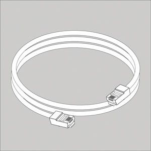
2 | RJ11 6P4C 2m CAN cable | 1 pc | |
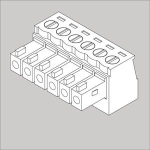
3 | Terminal 6P, pitch 3.5 mm | 8 pcs | |
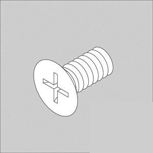
4 | Screws M3*8, flat head | 6 pcs | |
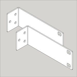
5 | 19" rack brackets | 2 pcs | |
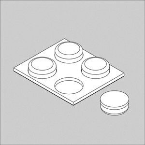
6 | Self-adhesive rubber foot | 4 pcs |
Package includes VT440
Included page https://vutlan.atlassian.net/wiki/spaces/DEN/pages/7209192/VT32+package+content
Make sure that the contents of the delivery meet the following configuration. Report a missing or damaged component to your supplier. If damage occurred during transportation, contact the appropriate delivery service.
Package content | Description | |
|---|---|---|
1 | Dry contacts board | |
2 | BH10 cable | |
3 | Terminal plugs 6*3.5 mm - 8 pcs | |
5 | Screws M3*5 mm - 3 pcs. |
Drawing
Installation
"TR" - is the nearest switch to CAN inputs. This switch should be turned "ON" on the last sensor in the CAN chain. The last sensor in the long chain with a length of more than 10 meters, the terminator should be in the "OFF" position.
pic.2.1: TR is ON, FR is OFF. pic.2.2: TR is OFF, FR is OFF.
Connecting CAN devices and sensors
Page linked https://vutlan.atlassian.net/wiki/spaces/DEN/pages/1016276/CAN+devices+connection
Setting up CAN
Page linked CAN configuration panel: setting up CAN
Copyright:
Vutlan s.r.o. (LLC)
Remote Infrastructure Monitoring and Control
43 ul.Svornosti, 821 06 Bratislava,
Slovak Republic
Frequently asked questions
Question | Answer |
|---|---|
What is the effective “max” distance that could be realistically supported to monitor Dry contacts? | Very long distances. Two kilometers are easily supported. |
|
|
Copyright:
Vutlan s.r.o. (LLC)
Remote Infrastructure Monitoring and Control
43 ul.Svornosti, 821 06 Bratislava,
Slovak Republic




(1.80).png?version=1&modificationDate=1636466707373&cacheVersion=1&api=v2&width=739&height=161)


