...
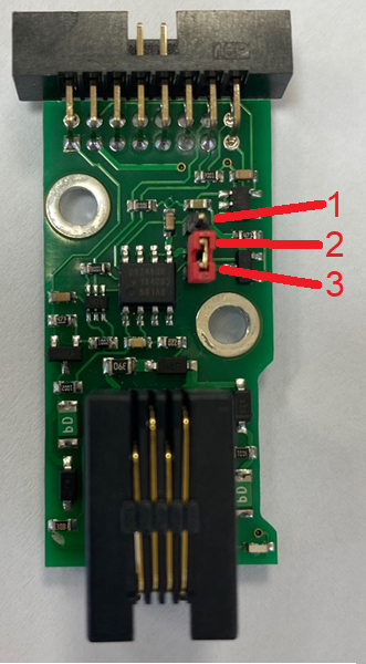
1b. Green LED. If the green light is "ON", then the 1-Wire board is on. There's an element inside monitoring unit's interface that can be switched "ON" and "OFF", which activates 1-Wire bus.
...
| Note |
|---|
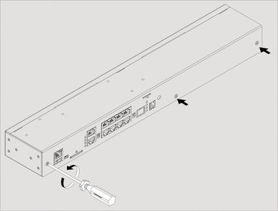
To install and to connect extension units: switch off the appliance, unplug from the outlet or disconnect the power connector. |
...
| 1 | Carefully unscrew screws holding the cover and open it.
| |||
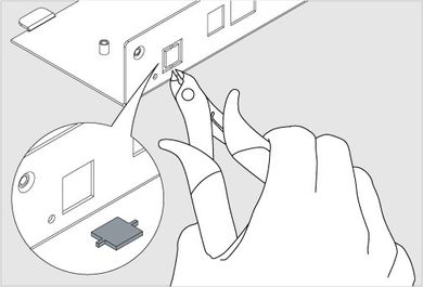
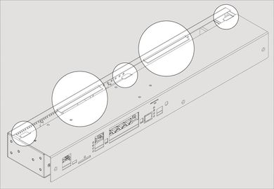
| 2 | Break 2 steel bridges in the 1-Wire hole of the appliance case (e.g. VT335 top metal)cover. Using forceps (cutter) with thin nozzles cut the thin bridges in the hole. Make sure that no burrs are left. | |||
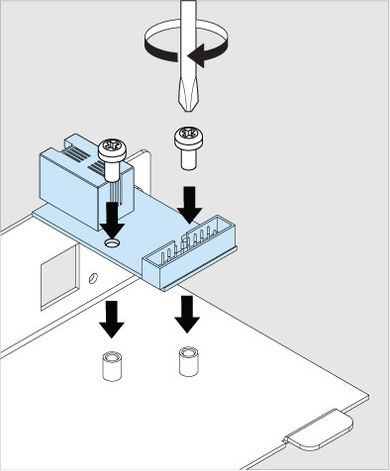
| 3 | Set up the 1-Wire board on 2 steel spacing sleeves inside the appliance case (e.g. VT335 top metal cover), attach the board with two M3 screws from supply to the sleeves. | |||
| 4 |
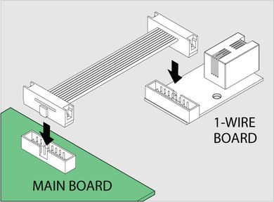
| Connect "16 wire IDC16 flat cable" supplied with a "1-Wire extension" board to the connector on the 1-Wire board and on main board the mainboard (e.g. VT335 board). Make sure is installed in 2-3 position | ||
| 6 | Close and fasten the cover. Carefully place top cover back so that all cover wings fit in and all cutoffpoints cutoff points match the panel holes. |
Activating 1-Wire interface:
After the "VT10 / 1-Wire board" has been installed inside the system, You need to check if the 1-Wire interface is On. Instructions can be found here: Setting up 1-Wire
...
All 1-Wire sensors are Plug&Play. Use the following examples for instructions on how to connect sensors:
...
You can use a range of accessories for the 1-Wire interface. Accessories are ordered separately.
...