Documentation page: https://vutlan.atlassian.net/wiki/spaces/DEN/pages/1834713171/VT500+Temperature35127341/VT490+Humidity+and+temperature+sensor+v2
Product page: https://vutlan.com/can-sensors/28-vt490-dual-humidity-and-temperature-sensor.html
.jpg?version=1&modificationDate=1611646749553&cacheVersion=1&api=v2&height=250)
.jpg?version=1&modificationDate=1611646748227&cacheVersion=1&api=v2&height=250)
Function and purpose
High quality humidity and temperature sensor with reliable price.
Technical specifications
Communications | Description |
|---|---|
| Sensor type | CAN digital sensor |
| Inputs/Outputs | x2 RJ11 6P4C ports |
| Daisy chain | Yes, daisy chain is possible for all CAN sensors. |
| Max. distance from the monitoring unit: | 225m |
| LED indicators: | Red / Green (RUN/ERR) |
Accuracy | |
| T accuracy: | ±0.4 °C (max), –10 to 85 °C |
| RH accuracy: | ± 3% RH (max), 0–80% RH |
| Resolution | 0,1 °C |
| Environmental | |
| Working temperature range: | −40 to +125 °С operating range |
| Humidity operating range: | 0 to 95% RH operating range |
| Power Requirement | |
| Power input: | 12V DC, 1A |
| Current consumption: | 1 Watt |
| Mechanics | |
| Dimensions: | 68x47x26 mm |
| Packaging weight: | 160 g |
| Mounting options: | Desktop, Wall mount |
| General | |
| Manufactured in: | Slovak Republic, European Union |
| Manufactured by: | Vutlan s.r.o. |
| HS code: | 9025 11 800 |
| Warranty: | 90 days |
Physical description
.jpg?version=1&modificationDate=1462274777786&cacheVersion=1&api=v2&width=250)
.jpg?version=1&modificationDate=1462274777673&cacheVersion=1&api=v2&width=250)
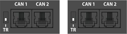
1. LEDs: "RUN" - indicates appliance connection status to the main module, "ERR" - indicates appliance lost connection to the main module.
2. "Humidity & temperature sensor" - Operating temperature: −40… +125°С; RH operating range: 0 to 100%; T accuracy: ±0.4°C in –10 to 85 °C range; RH accuracy: ± 3% RH in 0 to 80% range.
3. "TR" - is the the nearest switch to CAN inputs. This switch should be turned to "ON" on position if the sensor is the last sensor in the CAN chain. The last sensor in long chain with length more then 10 meters, terminator should be in "OFF" position.
Example 1: We have 1 CAN sensor connected to the main module VT8101 on the " CAN 1" bus. In this case, this sensor is the only one and the last one in the CAN chain and its 2nd "TR" switch should be in the "ON" position.
Example 2: We have 5 sensors or modules connected to the main module via the " CAN 1" bus and a sensor or module bus. The sensor is not the last sensor in a chain, for example, it is located in the middle of teh chain. In this case, the "TR" switch must be in the "OFF" position.
Example 2: We have 5 sensors or modules connected to the main module via the " CAN 2" bus. In this case, the 2nd The sensor is the last sensor in a chain. The "TR" switch must be in the "ON" position.
4. "CAN" - two equivalent digital connectors RJ12 for the connection to the master module, CAN sensors or CAN extensions on a CAN bus, with auto-sensing.
...
| View file | ||||
|---|---|---|---|---|
|
Connecting the sensor
...
Connecting CAN devices
| Include Page | ||||
|---|---|---|---|---|
|
CAN configuration
| Include Page | ||||
|---|---|---|---|---|
|
Packaging includes
| Include Page | ||||
|---|---|---|---|---|
|
API: managing system elements by 3rd party Software
Vutlan has an open API. Read more at:
https://vutlan.atlassian.net/wiki/spaces/API/pages/335740995/Managing+system+elements
Copyright:
Vutlan s.r.o.
Remote Infrastructure Monitoring and Control
43 ul.Svornosti, 82106 Bratislava,
Slovak Republic, E.U.