Latest Vutlan drivers (from August 2021) support Modbus RTU read and write functions for all monitoring systems.
.png?version=2&modificationDate=1696235938117&cacheVersion=1&api=v2&width=204&height=209) | .png?version=1&modificationDate=1696235938876&cacheVersion=1&api=v2&width=102&height=259) |
Function and purpose
It is an extension PCB board and should be purchased separately.
Allows to monitor up to 32 Modbus RTU devices/meters/sensors. The maximum distance of a daisy chain is up to 1000 meters. Each metered value of a Modbus device is addressed individually using input registers and is shown by the system as virtual sensors. You can configure thresholds and icon representations for these elements.
It can be used with VT335t, VT336t, VT825t, and VT855t monitoring systems. A slot PCB board can be inserted inside the monitoring unit while the unit is in operation. Has an internal termination and by default, it is switched ON (if required can be turned off).
Physical description
By default, the terminator on the board of VT335t, VT825t, and VT855t is always ON.

a) "RS-485 Status" - LED for displaying Modbus RTU port status.
b) "B-, A+, GND" - port for connecting Modbus RTU devices.
Connecting Modbus RTU sensors:
Example 1: Daisy chain connection (the main controller is located at the beginning of the chain)
Sensors are connected in a daisy chain connection.
120Ω resistor is used at the end of the chain which is equal to the resistance of the cable.
A twisted pair cable is used for A(+) and B(-).
"VT335t, VT825t, and VT855t monitoring units" have an internal termination, and by default, it is switched to the ON position. (If it is required, it is possible to switch it OFF)
Up to 32 devices can be used.
Overall cable length is no more than 1000 meters.

| VT485r | Cables | Eastron SDM220-MODBUS |
|---|---|---|---|

| B- | red | +12V |
A+ | blue | A+ | |
GND | white | GND |
Physical description
Example 2: (Not recommended) Daisy chain connection (the main controller is located in the middle of the chain)
"VT335t, VT825t, and VT855t monitoring units" have an internal termination, and by default, it is switched ON.
Switch off the Vutlan monitoring unit.
Open the enclosure’s bottom and pull the mainboard from the enclosure.
Find a Modbus jumper and take the cap off.
Put everything back together.
Now it is possible to connect the Modbus sensors in a daisy chain with the Vutlan monitoring unit in the middle of the chain.
Sensors are connected in a daisy chain connection.
120Ω resistor is used at the ends of the chain which is equal to the resistance of the cable.
A twisted pair cable is used for A(+) and B(-).
Up to 32 devices can be used.
Overall cable length is no more than 1000 meters.
-02.jpg?version=1&modificationDate=1696232683567&cacheVersion=1&api=v2)
Activation and Configuration of Modbus interface:
After all Modbus devices have been connected to it, you need to activate it and configure:
Related articles
Connecting "VT85 / Modbus extension board"
Connecting Modbus sensors using "RS485 to USB adapter"
Introduction
A virtual "Modbus RTU" sensor is used to read and write data from external equipment via Modbus RTU protocol (RS-485 line). Such equipment can be sensors/meters or devices/systems/units.
Some Vutlan devices have a Modbus RTU port. Some require an additional extension to be bought separately.
Some older Vutlan units use an external converter to the USB bus is used to provide RS-485 communication.
https://vutlan.atlassian.net/wiki/spaces/DEN/pages/678887425/Creating+virtual+Modbus+RTU+element
Activating Modbus
After connecting the RS485 bus, according to the "Slave" hardware documentation, you can now activate the Modbus.
The Modbus operates in "Master" mode. To enable Modbus, go inside the web interface of the Vutlan monitoring unit and go to the Preferences menu >> Modbus RTU. Set up the bus according to the documentation for the "Slave" equipment. Please note that the "VT85 / Modbus extension board" only supports 1 stop bit.

Adding the Modbus reading virtual element
To create a "Modbus RTU (reading)" element, press add button "  " inside the "Group tree" or "System tree" menu. Then choose "Modbus RTU (reading)". A modal window will appear:

Click on the "Modbus RTU (reading)". Modbus element form will be opened:

Fields in the form available for change:
# | Name | Description |
|---|---|---|
1 | Name | Created element name |
2 | User-defined type | Defines the icon to be displayed in the "System tree" |
3 | Units of measurement | The unit of measure in which the value is displayed in the "System tree" |
4 | Minimum value | Determines the minimum measurement range, when the value is out of range, the sensor goes into the "Not connected" state |
5 | Maximum value | Determines the maximum measurement range, when the value is out of range, the sensor goes into a "Not connected" state |
6 | Alarm and warning levels | Defines the alarm and warning thresholds, as for other sensors, see Sensor configuration |
7 | Hysteresis | Option of setting the hysteresis state, see Sensor configuration |
8 | Expression | Function of the form f (x). The default value for the sensor is equal to the measured value: "x", ie corresponds to the expression "x". To calculate the indirect value of the sensor is possible to use an arbitrary expression, which is permissible "(", ")", as well as:
For example: "0.1*x+0.5" |
The Modbus RTU bus configuration is available in the "Additional" tab:
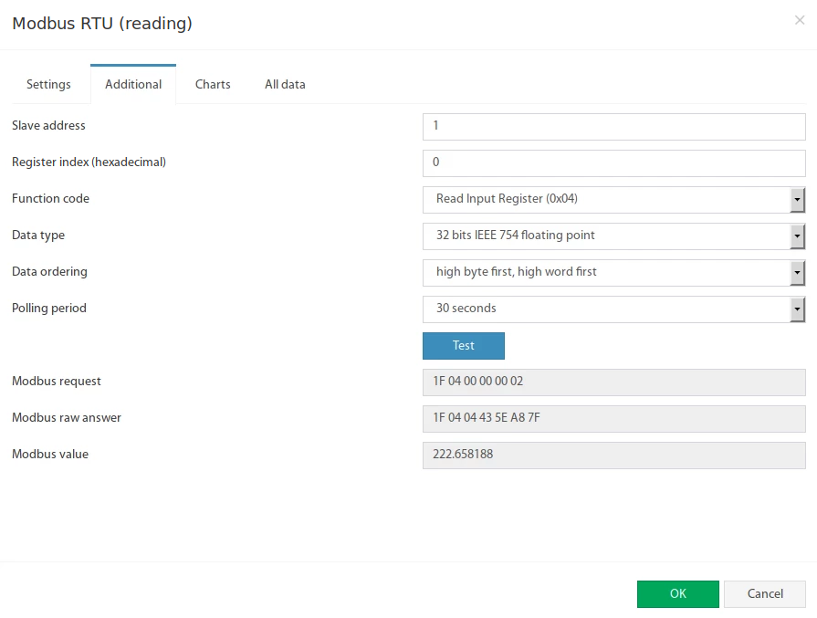 Fields in the form available for change:
# | Name | Description |
|---|---|---|
1 | Slave address | Modbus RTU slave address of external equipment |
2 | Register index | Modbus protocol register start address in hexadecimal view, like 0F4A |
3 | Function code | The following functions are supported:
|
4 | Data type | Determines how to present the data:
|
5 | Data ordering | Determines byte order in Modbus protocol response message:
|
6 | Polling period | Defines the time of polling the sensor value. From 10 seconds to 5 minutes. |
The Test button allows you to make a test connection with a Modbus device. In additional fields, the bytes sequence of connection, data is displayed, in hexadecimal form. Modbus request - data of the sent request, without a checksum. Modbus raw answer - data of the received answer, without a checksum. Modbus value - contains the data value interpreted under the selected Data type.
Adding the Modbus writing virtual element
To create a "Modbus RTU (writing)" element, press add button " " inside the "Group tree" or "System tree" menu. Then choose "Modbus RTU (writing)". Modbus element form will be opened:
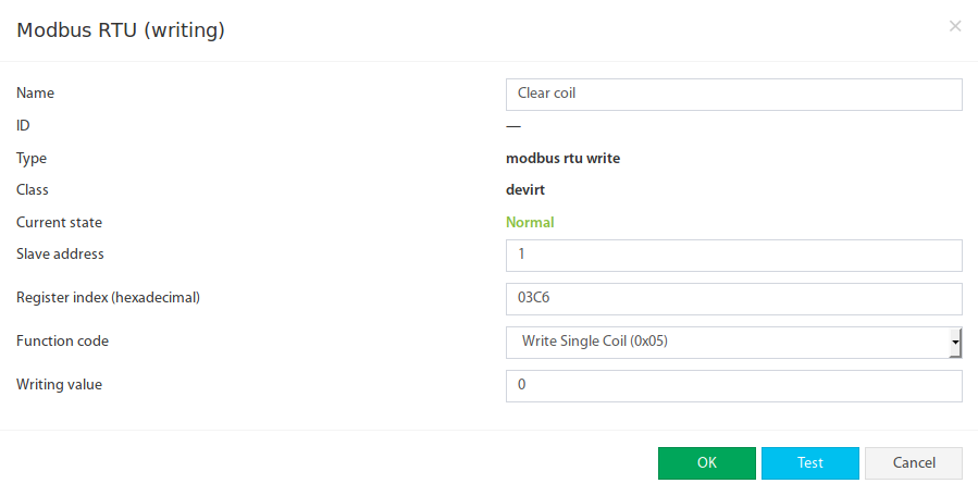
Fields in the form available for change:
# | Name | Description |
|---|---|---|
1 | Name | Created element name |
2 | Slave address | Modbus RTU slave address of external equipment |
3 | Register index | Modbus protocol register start address in hexadecimal view, like 0F4A |
4 | Function code | The following functions are supported:
|
5 | Writing value | Decimal integer value that will be written in the specified register |
The Test button allows you to make a value entry immediately into the Modbus register. Now the Modbus RTU writing can be inserted as a THEN task in logic schemes:

Modbus configurations for tested sensors
See the article Modbus configuration for tested sensors
Accessories:
You can use a range of Sensors/Meters/Devices for Modbus.