Product page: https://vutlan.com/remote-monitoring-units/108-vt335s-monitoring-unit.html
 End of Life: 01.08.2022

1. "CAN" - digital connector RJ12 for the connection of CAN sensors and CAN extensions on a CAN bus, with auto-sensing.
2. "LAN" - Ethernet 10/100 Base-T port, provides an Ethernet connection.
• LEDs - "yellow" (status) and "green" (traffic) show the network traffic. The status LED: flashes green when the system starts up, and shows the connection state (constant green light - the connection is established, blinking green - the connection attempt).
3. "USB" - type miniAB USB-port 2.0, required to connect a USB camera or to restore an appliance.
4. This is a slot for "VT760 / Internal LTE modem". The modem is purchased separately!
4a. LED: "MODEM STATUS" - indicates SIM card status. Blinking = working. (VT760 / Internal LTE modem is ordered separately)
4b. "Main antenna" - Connector, used when the LTE modem is installed inside of the appliance to connect the LTE main antenna. (The main antenna is supplied together with the modem).
"Auxiliary antenna" - Connector, used when the modem is installed inside of the appliance to connect the LTE auxiliary antenna. The additional antenna helps to strengthen the signal level. (Auxiliary LTE antenna and antenna output are ordered separately from the modem).
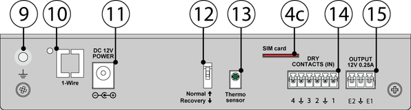
4c. "SIM card" - SIM card slot with an injector.
5. "A1..A4" - 4 RJ12 analog sensor inputs with auto-sensing.
6. LEDs: "ACT" - indicates appliance status, "E1" - indicates 12V E1 relay status, "E2" - indicates 12V E2 relay status, and "ERROR" - indicates error and traffic.
• Blinking "ACT" ............ • Blinking "E1" ............ • Blinking "E2"............ • Blinking "ERROR" ..........
7. "RESTART" - restarts the appliance.
8. LED "CAN" for digital bus sensors:
"CAN" blinks slowly - nothing is connected
"CAN" blinks fast - configuration is in process
"CAN" glows constantly - connected to CAN devices
9. " " - External chassis grounding, M4 thread.
10. "1-WIRE" - can be used with VT10 / 1-Wire extension board". Allows connecting 1-Wire reader or 1-Wire temperature sensors in serial line. Has "1-WIRE" status led.
11. "DC 12V 2A" - DC power input.
12. "Dip switch" Normal ↑ Off - the system should be always switched to this mode.
Recovery ↓ On - use this option only in case you need to recover manufacturing settings.
13. "TEMPERATURE SENSOR" - accuracy +/- 1 °C.
14. "DRY CONTACTS 1...4" - Dry contacts terminal (type IN)
15. "OUTPUT 12V 0.25A" - 12V 0.25A output electronic relay terminal
Package content
Make sure that the contents of the delivery meet the following configuration. Report a missing or damaged component to your supplier. If damage occurred during transportation, contact the appropriate delivery service.
Package content | Description | |
|---|---|---|
1 | 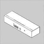 | Monitoring unit VT335. |
2 | 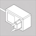 | 12V adapter. |
3 | 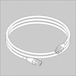 | RJ-45 3m patch cable |
4 | 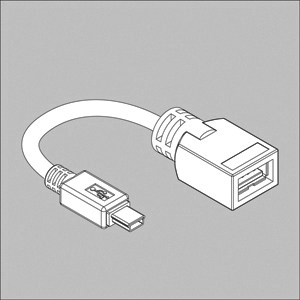 | USB adapter cable |
5 | 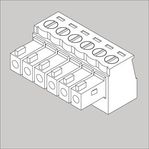 | Terminal plug 6 pins, 3.5 mm - 1 pcs |
6 | 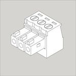 | Terminal plug 3 pins, 3.81 mm - 1 pcs |
7 | 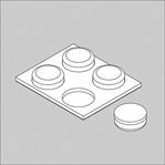 | Self-adhesive rubber foot - 4 pcs |
8 |  | Configuration manual |
9 |  | Warranty card |
Developer notes: metal case VT335 v2.1