Logic schemes are used to specify automatic actions to events that occur in schemes are used to specify automatic actions to events that occur in the system.
| Note |
|---|
Attention! if you need to set up to get notified notifications on changes in more than one element, better use of the group notification |
Logic schemes represent a set of conditions "IF" and a set of actions that are executed "THEN". Conditions can be combined using "AND" and "OR". To carry out the actions it is possible to set the required action repeat timeout. If timeout equals 0 the action will be executed once.
...
| Info |
|---|
If the logic scheme is disabled the reverse actions of actions in "THEN" will not be executed. To execute reverse actions you have to set up a new logic scheme. |
...
...
Add a new logic scheme
To add a new logic go to "Main menu" >> "Logic schemes" >> and press add button "  ". A modal window will pop up.
...
Create a set of conditions "IF". Select the name of the element in "Element" and the state of the element in "State" as a condition for logic. To add a condition use "AND" or "OR" in the field "Operator".
| Info |
|---|
If a sensor with an analog output changes its state very rapidly (e.g. vibration sensor), the state of the element can change from "Low alarm" to "High alarm" and vice versa, without going through the state of without going through the state of "Warning", and and "Normal". |
Create a set of executable actions "THEN". Select the name of the element in "Element" and the state of an element in "State" columns into which element goes after the logic is triggered.
If necessary, in "Timeout" field, specify the time in seconds to create a pause before the element switches into the new state after execute the “Timeout" field, specify the time in seconds to create a pause before the element switches into the new state after the logic is triggered.
| Info |
|---|
If, within the specified time-out logic is deactivatedwithin the specified time-out logic is deactivated, the element will not change its state. |
In the "Repeat" field, you can set the repetition period of the action for the entire duration of the activity of the logic scheme (for example, periodic message sending).
Save created logic.created logic.
| Note |
|---|
Remember to save the settings of elements and logic schemes in the flash memory of the device. Press " |

One-time actions
You can create logic schemes for one-time actions when booting the system:
...
Under given conditions, you can force a reboot of the system by the logic scheme. Use this function more carefully if you save the log files to an e-mail or FTP server. The The system will not reboot if less than 15 minutes have elapsed from the system start.
...
Temporary disable/enable all available logic schemes
At the top of the logic schemes panel, there are buttons for temporarily disabling and enabling all available logic schemes at once.
...
Example 1
For example, we want to:
use an AC sensor to alert when power is
...
‘OFF’
alert when the power is
...
‘ON’ again
...
schedule an activity if the blackout is longer than the setup limit.
Create three triggers that correspond to the three monitored states:
- Power ON
‘Power ON’ - corresponds to the state when the power is on;
- Power OFF
‘Power OFF’ - corresponds to the state when the power was turned off (shortly);
- Blackout
‘Blackout’ - corresponds to a state when there is no power for a long time, to consider this situation emergency.
...
Set the voltage sensor settings under the task. Power off will be detected by the lower threshold "Low alarm" greater than zero, because when the power is turned off, the sensor may continue to detect voltages of several volts.
...
Create a logic scheme for monitoring a power failure. If the power is lost, the AC sensor will enter the "Low alarm" mode. In this case, turn on the “Power OFF” trigger and turn off the “Power ON” trigger.
...
The trigger "Blackout" is turned on if there is no power for a long time, for example, 15 minutes. To set the time, use the "Timeout" field, if the power is restored before this time, the logic scheme will not be activated. This situation is handled by the following logic scheme:
...
Finally, create a logic circuit to turn on the power. It should turn off the triggers "Power OFF" and "Blackout" if the power is within normal limits, i.e. AC sensor is in any working condition except "Low alarm".
...
Now three triggers reflect the current state of the observed voltage. To inform the administrator, you can connect to their logic schemes by sending notifications. In the case of a Blackout, sending a notification will be repeated every half hour (use the "Repeat" field) until power is restored.
...
Example 2
For example, you have a telecommunication rack with servers and equipment. You need to activate fans inside a rack when the temperature reaches 36°C. If the temperature reaches 44°C you need to activate fans, alarm the siren on for 90 seconds, and notify the administrator via e-mail and SMS.
You have:
# | Device | Description |
|---|---|---|
1 | Temperature | Temperature sensor installed inside a rack |
2 | Power-1 Fun | Controls fans |
3 | Power-2 Alarm | Controls siren alarm |
4 | Mail admin | Notification via e-mail. Created by user |
5 | SMS admin | Notification via SMS. Created by user |
1. Edit the thresholds of "High warning" and "High alarm" levels for the temperature sensor. Set "High warning level" to 36°C and "High alarm level" to 44°C, with useless "Low" thresholds set to minimum.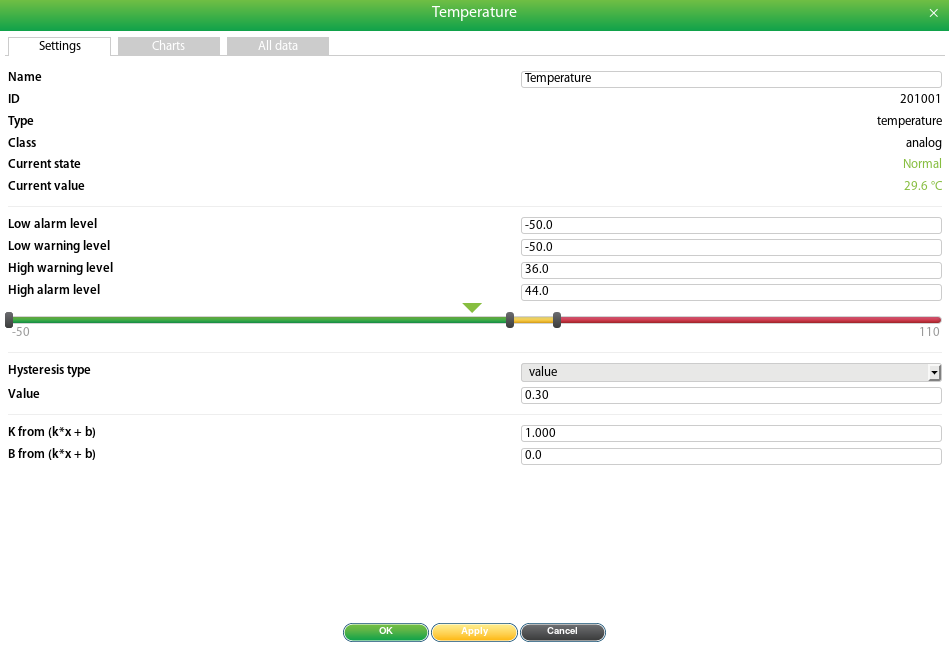
...
2. Configure relay settings. Choose a name and set "Pulse duration", it determines the time at which the alarm will be activated.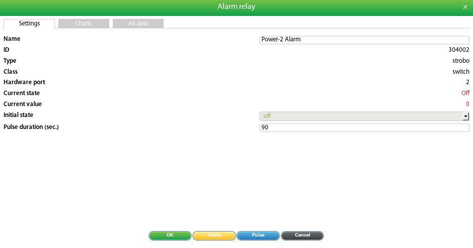
...
3. Create "E-mail" and "SMS" notifications. Follow the steps in the section: Creating notifications.
4. Go to the "Logic schemesSchemes" menu. Add 3 logic schemes as follows:
...
a. First logic scheme will turn on "Power-1 Fun" when the temperature reaches 36°C (high warning level).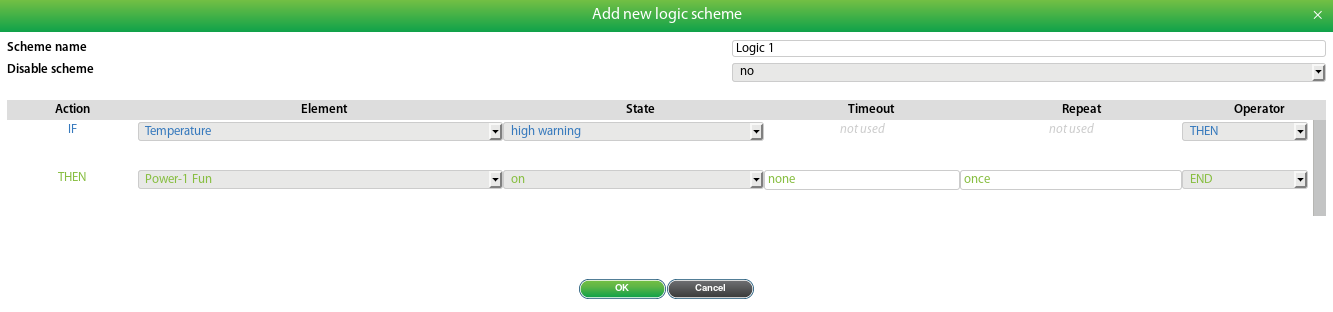
...
b. Second logic scheme will turn on the "Power-1 Fan" when the temperature reaches 44°C (high alarm level). The "Power-2 Alarm" is switched to pulse on for 90 seconds, as it was previously configured. SMS and e-mail notifications will be sent.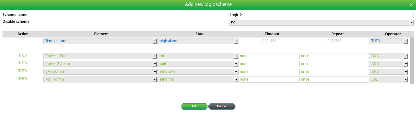
...
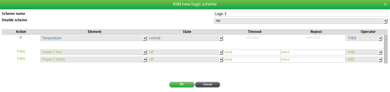
c. Third logic will turn off the "Power-1 Fan" and "Power-1 Alarm" when the temperature falls into "normal" ("Normal" level is between "low warning" and "high warning" levels. Thus below 36°C in this example).
...
'Group' settings
Logic notifications can also be created using built-in "Group" settings: Using group notificationsPrevious UI versions:
| Child pages (Children Display) |
|---|