...
Connect CAN devices to any port CAN1 or CAN2 on the monitoring system using a cable supplied. CAN sensors can also be connected to the port of another CAN sensor or CAN unit which is connected on to the CAN bus. Determination of the devices and their connection is done through a web - interface.
Info You can connect up to a maximum of 8 x12 CAN sensors and CAN devices together on one CAN bus (approximately) !
If you want to connect more than x12 CAN units, you need to use CAN-12V-1A / CAN Power Supply
The TR should be "ON" for the last sensor on each bus "CAN 1" and "CAN 2". See section "TR" below.
...
| Note |
|---|
Only older Vutlan models have an FR switch. |
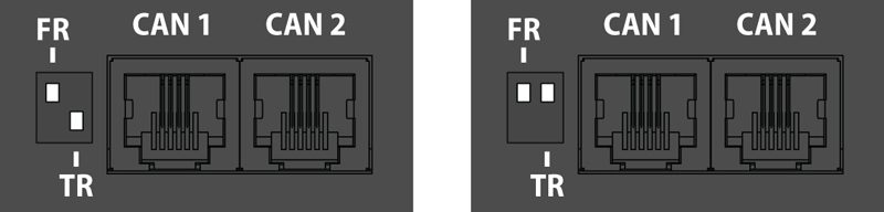
pic.1.1: FR is OFF, TR is ON. pic.1.2: FR is OFF, TR is OFF.
Adding CAN modules and sensors
To connect the CAN module or CAN sensor to the CAN bus of the system, go to the interface >> CAN configuration panel >> Select the CAN1 or CAN2 tab (select the connected physical CAN1 or CAN2 port on the master module).
...
| Warning |
|---|
Warning: If the bus is not matched, that is, there are bad contacts or bad cables, or the TR terminator is in the"ON" position on the intermediate devices (position 2 on the VT408), or the line is too short for matching on both CAN end devices, CAN on this line can work malfunctioning or the line as a whole may not function. (CAN line failure may occur if the parallel CR switch is in state 1, must be in OFF). |
...