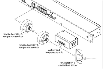
CAN sensors and CAN units connection
Connect CAN devices to any port CAN1 or CAN2 on the monitoring system using a cable supplied. CAN sensors can also be connected to the port of another CAN sensor or CAN unit which is connected on the CAN bus. Determination of the devices and their connection is done through web-interface.
You can connect up to a maximum of 8 CAN sensors and CAN devices together on one CAN bus (approximately) !
The TR should be "ON" for the last sensor on each bus "CAN 1" and "CAN 2". See section "TR" below.
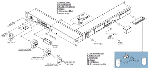
This procedure applies to the following sensors, which are supported by the appliance and are connected to the CAN ports:
CAN sensors, modules:
- VT408 / Extension unit
- VT430 / Rack control unit
- VT440 / Dry contacts unit
- VT460 / Smoke, humidity, and temperature...
- VT470 / PIR, vibration and temperature sensor
- VT490 / Humidity and temperature sensor
- and other...
CAN extension unit:
Read more about Setting up CAN sensors.
Used cable and limit line length
The maximum length of the CAN line in Vutlan monitoring systems is 225 m due to limitations on the ohmic resistance of cables with RJ12 connectors.
It is advisable to use two or three pairs of cables such as UTP Cat3.5.6 with 24AWG with a copper core. It is possible to use a 4-wire or 6-wire TRONIC or UTP CCA cable, but the maximum CAN line length will be reduced.

TR termination switch
The last sensor TR switch on a CAN chain must always be terminated, ( switched ON ). Sensors on a CAN bus that is in the middle should have TR switched OFF.
FR should always be OFF.
TR switch is always the DP switch nearest to the CAN bus.
Only older Vutlan models have FR switch.
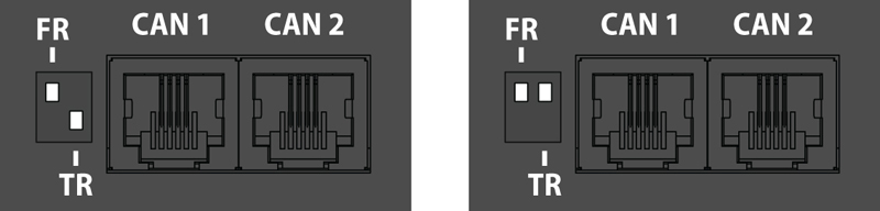
pic.1.1: FR is OFF, TR is ON. pic.1.2: FR is OFF, TR is OFF.
Adding CAN modules and sensors
To connect CAN module or CAN sensor to the CAN bus of the system, go to the interface >> CAN configuration panel >> Select the CAN1 or CAN2 tab (select the connected physical CAN1 or CAN2 port on the master module).
Click the "Configure" button and wait. The system will start CAN bus polling, soon it will display the data lines and write “Done!”. The modules and sensors connected to the CAN input will appear in a tab in the list. Click the Apply button and then Restart.
The green LED "CAN status" of the device will light up.
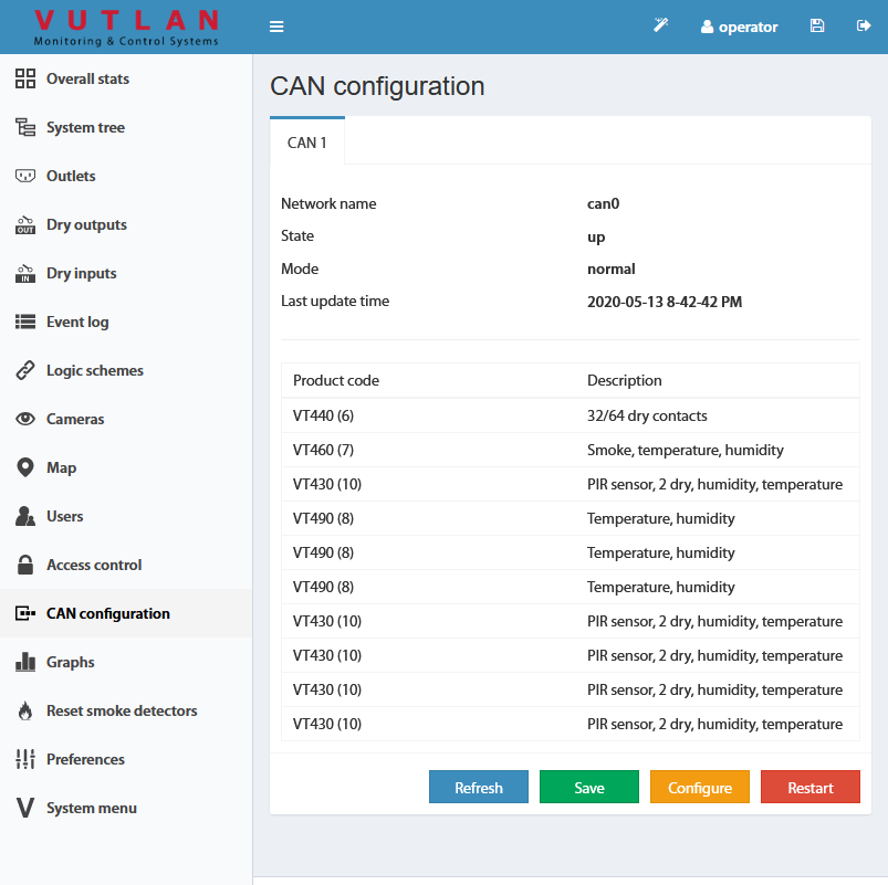
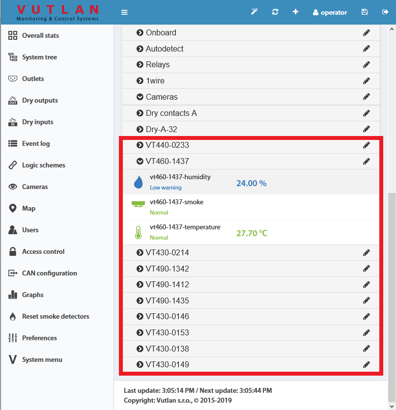
Go to panel "System Tree" to see the new devices or new sensors. The article numbers for CAN devices are VT4xx. If they do not appear, wait, or refresh.
If after clicking the "Configure" button the poll is reset to the phrase "Update", then the line is not connected or the terminators on the bus are not agreed. It is necessary to check and change the condition of the TR terminators (See "TR termination switch" section above) on the modules or check and possibly change the connection cables.
Warning: If the bus is not matched, that is, there are bad contacts or bad cables, or the TR terminator is in "ON" position on the intermediate devices (position 2 on the VT408), or the line is too short for matching on both CAN end devices, CAN on this line can work malfunctioning or the line as a whole may not function. (CAN line failure may occur if the parallel CR switch is in state 1, must be in OFF).
LEDs
CAN sensors have LEDs that indicate the following states:
Red continuous light, green flickers - no communication with the master module
Red continuous light, green is off - there is a connection with the master unit, but is not included in the monitoring system (not configured)
Red is off, Green continuously light - work as part of a monitoring system
- All LEDs are off: no power or sensor is defective.
Maximum cable length test
| Model | Description | 50m | 100m | 150m | 200m |
|---|---|---|---|---|---|
| VT408 | Sensor extension unit | ok | |||
| VT408DIN | ok | ||||
| VT430 | Rack control unit | ok | |||
| VT440 | Dry contacts unit | ok | |||
| VT460 | Smoke, humidity, temperature | ok | |||
| VT490 / VT490i | Dual humidity and temperature sensor / Pressure, humidity & temperature sensor | ok |
see also: