...
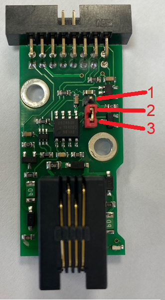
1b. Green LED. If the green light is "ON", then the 1-Wire board is on. There's an element inside the monitoring unit's interface that can be switched "ON" and "OFF", which activates the 1-Wire bus.
Connection
Monitoring units have the option of installing a "VT10 / 1-Wire board" (expansion board). The board is mounted and connected inside the monitoring unit. 1-Wire technology is based on a serial communication protocol that uses one data line and a reference ground between the master (for example, the VT335 / Monitoring Unit) and one wire slave.
Installation and connecting of VT10 1-Wire board
| Note |
|---|
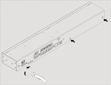
To install and to connect extension units: switch off the appliance, unplug from the outlet or disconnect the power connector. |
...
| 1 | Carefully unscrew screws holding the cover and open it.
| |||
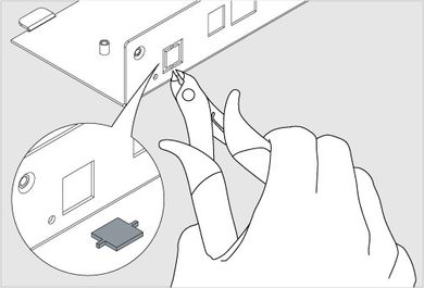
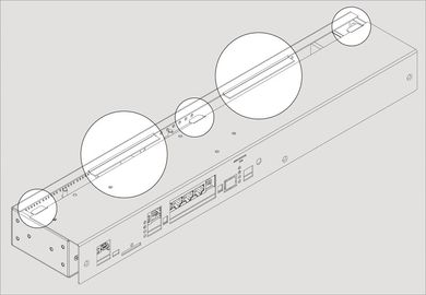
| 2 | Break 2 steel bridges in the 1-Wire hole of the appliance case (e.g. VT335 top metal)cover. Using forceps (cutter) with thin nozzles cut the thin bridges in the hole. Make sure that no burrs are left. | |||
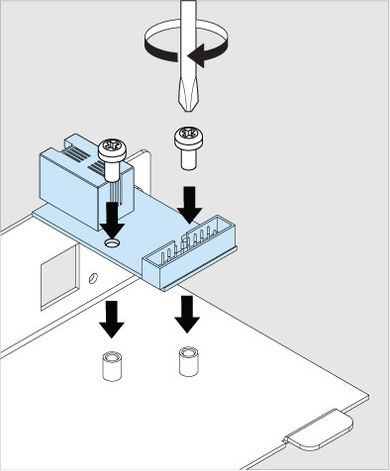
| 3 | Set up the 1-Wire board on 2 steel spacing sleeves inside the appliance case (e.g. VT335 top metal cover), attach the board with two M3 screws from supply to the sleeves. | |||
| 4 |
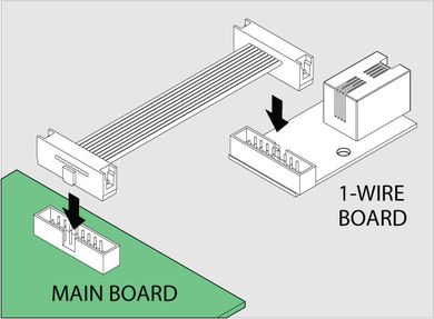
| Connect "16 wire IDC16 flat cable" supplied with a "1-Wire extension" board to the connector on the 1-Wire board and on the mainboard (e.g. VT335 board). Make sure is installed in 2-3 position | ||
| 6 | Close and fasten the cover. Carefully place the top cover back so that all cover wings fit in and all cutoff points match the panel holes. |
...