...
DIN rail extension, wall brackets are purchased separately.
Installation
- Connect any CAN
...
- port of the unit by RJ11 6P4C cable supplied to the CAN
...
- port of the previous CAN unit or the monitoring system. The red LED lights up.
...
- If this CAN device is the last in CAN bus chain, then switch the Termination ON. If not, keep it Off.
- If the unit is far 10m away from the monitoring unit or more, connect an additional auxiliary power supply. In all other cases, the use of an external power supply is desirable.
Dimensions for wall mounting:
Configuration
To connect CAN unit to the system, open interface and go 
Click "Configure" and wait. The system starts the CAN bus line survey, display the list of connected CAN units and sensors. On the CAN devices, the green LEDs lights up.
If you will go now to the "System tree", you will see there new CAN devices and/or new CAN sensors. Wait a little or renew tree.
If the survey is reset after click "Configure", it means that the line is not connected (bad cable and / or bad connectors) or not matched terminators on the bus. It is necessary to check and change the status of line or the TR terminations.
Analog sensors are connected to the A-1 ... A-8 analog inputs on the module, the definition of the sensors will occur automatically.
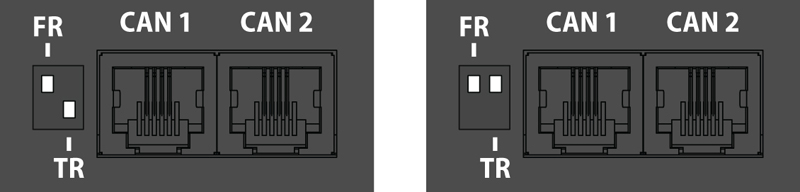
pic.1.1: FR is OFF, TR is ON. pic.1.2: FR is OFF, TR is OFF.
...
Example connection:
.jpg?version=1&modificationDate=1596449632974&cacheVersion=1&api=v2&width=800)
Indication
The VT408 expansion module has two RUN and ERROR LEDs that show the following states:
...
...
CAN setting
The extension module has a built-in element:
- Power - the element of relay
This element, by designation, is identical to the Analog Power element of the monitoring module. It turns on or off the power of the analog sensors.
The analog sensor power off for a few seconds is used to reset the alarm of the VT560 smoke detectors connected to the VT408 expansion module.
Warning: when the analog sensors are powered off, all external sensors connected to the VT408 cease to function.
The analog sensors connected to the VT408 are configured in the same way as the sensors connected to the monitoring module.
(Developer notes: physical description : metal case v 14.3 )