The unit can be found on our official website at: VT408DIN / Sensor extension unit
Physical description
Module VT408DIN is designed to expand the number of analog sensors connected to monitoring systems.
.jpg?version=1&modificationDate=1596454571545&cacheVersion=1&api=v2&width=800)

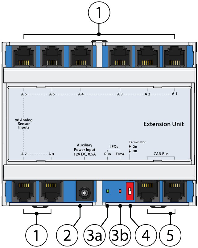
1. "A1..A8" - x8 RJ11 6P4C analog sensor input ports with auto-sensing.
2. "Power" - for connection of external power supply 12V DC, 05A.
3. LEDs:
3a. "RUN" - indicates appliance connection status to the main module,
3b. "ERROR" - indicates appliance lost connection to the main module.
ERROR is lit continuously, RUN blinks - the unit has no connection with the monitoring unit.
ERROR is continuously lit, RUN repaid - extension unit communicates with monitoring unit, but it is not included in the monitoring system (not configured).
ERROR repaid, RUN lights up continuously - the extension unit is included in the work as part of a monitoring system.
4. "Terminator" - This switch should be turned "ON" on the last sensor/device in the CAN chain.
5. "CAN bus" - x2 equivalent digital RJ11 6P4C connectors for the connection to the master module.
Function
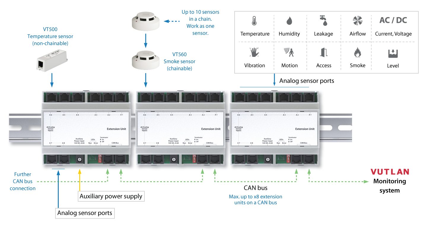
VT408DIN module is developed to expand the number of analog sensors connected to the monitoring system. The picture below illustrates the expansion example:

Mounting
DIN rail mounting
- There are DIN rail mounting hooks at the top and the bottom of the case. Pull them outwards.
- Press the enclosure against the DIN rail so that it fits behind the enclosure.
- Tap the hooks back in to snap to the DIN rail.
.jpg?version=1&modificationDate=1596458306926&cacheVersion=1&api=v2&width=1000)
DIN rail unmounting
- Use a screwdriver and pull the x3 hooks on the enclosure outward.
- Pull the enclosure away from the DIN rail.
-05-06.jpg?version=1&modificationDate=1596454574125&cacheVersion=1&api=v2&height=250)
.jpg?version=1&modificationDate=1596454573210&cacheVersion=1&api=v2&width=400)
DIN rail extension, wall brackets are purchased separately.
Installation
- Connect any CAN port of the unit by RJ11 6P4C cable supplied to the CAN port of the previous CAN unit or the monitoring system. The red LED lights up.
- If this CAN device is the last in the CAN bus chain, then switch the Termination ON. If not, keep it Off.
- If the unit is far 10m away from the monitoring unit or more, connect an additional auxiliary power supply. In all other cases, the use of an external power supply is desirable.
Configuration
Setting up CAN
Configuring VT408
CAN setting
The extension module has a built-in element:
- Power - the element of relay
This element, by designation, is identical to the Analog Power element of the monitoring module. It turns on or off the power of the analog sensors.
The analog sensor power off for a few seconds is used to reset the alarm of the VT560 smoke detectors connected to the VT408 expansion module.
Warning: when the analog sensors are powered off, all external sensors connected to the VT408 cease to function.
The analog sensors connected to the VT408 are configured in the same way as the sensors connected to the monitoring module.
(Developer notes: )
.jpg?version=1&modificationDate=1596454571545&cacheVersion=1&api=v2&width=800)
.jpg?version=1&modificationDate=1596454571545&cacheVersion=1&api=v2&width=800)


.jpg?version=1&modificationDate=1596458306926&cacheVersion=1&api=v2&width=1000)
-05-06.jpg?version=1&modificationDate=1596454574125&cacheVersion=1&api=v2&height=250)
.jpg?version=1&modificationDate=1596454573210&cacheVersion=1&api=v2&width=400)