Product page: https://vutlan.com/motion/173-vt470-radar-motion-vibration-and-temperature-sensor.html
Datasheet page: https://vutlan.atlassian.net/l/cp/hbgCqy8S
Function and purpose
A high-performance sensor/detector using microwave radar as a control signal source to detect objects or human movement. This product is an indoor energy-saving high-sensitivity detector.
The scanned signal can penetrate plastic, glass, ceiling, wooden door, and thin walls.
The sensor also has a built-in vibration and humidity sensors.
The maximum amount of sensors connected to the Vutlan monitoring unit and maximum length can be extended using the "VT408 / Sensor extension unit" or “VT408DIN / Extension unit”.
Microwave radar vs PIR
Why Microwave motion sensor? Quick response time, Higher accuracy than PIR, The scanned signal can penetrate plastic, glass, ceiling, wooden door, and thin walls. This microwave motion sensor reflects the latest development in motion detection technology.
Example: Air-conditioning can be a problem for PIR sensors, especially in rooms adapted for server rooms, where sensors are activated by violent gusts of air. That is why using microwave radar detectors makes sense.
Physical description
1. "CAN" - two equivalent digital RJ12 ports for connecting CAN sensors and CAN extensions to a common bus. The order of connection does not matter.
2. Temperature sensor.
3. "Wall holder" - attachment place
4. "TR" - CAN bus terminator. If this is the last sensor in a CAN chain, use the “ON” position. Otherwise, use the “OFF” position.
5. "Wall holder part 2"
6. “Wall holder part 1”
7. “Wall holder part 1” and “Wall holder part 2” connected together
8. Indicators:
"Green" - shows the status "Normal" (no movement detected)
"Red" - shows the status "Alarm" (movement detected)
9. "Motion window" - The motion sensor movement detection window.
Technical specifications
General parameters | Description |
Type: | CAN digital sensor |
Usage: | Motion, movement, position, proximity detector/sensor. Temperature detection. Vibration detection. |
Technology: | Motion: Doppler Principle (transmit and receive signals) using microwave radar with minituarized planar antennas |
Daisy chain connection: | Yes, possible with different CAN sensors and modules. |
HS Code: | 8531 80 950 |
Manufactured in (country): | Manufactured in Slovak Republic, E.U. |
Certification standards: | FCC/CE/SRRC/RoHS |
LEDs: | Red when movement detected. Green when no movement detected. |
| |
RF parameters | Description/value |
Frequency Range: | 5.725GHz-5.875GHz |
Transmit Power: | -4dBm |
Antenna: | Built-in flat antennas |
| |
Temperature sensor | Description/value |
Tolerance: | ±1 ℃ |
Hardware parameters | Description/value |
Operating Temperature: | Sensor PCB board: from -20 ℃ to +85 ℃ ABS plastic enclosure: from -20 ℃ to +80 °C PVC RJ cable: from -15 ℃ to +80 °C |
Storage temperature: | from -40° С to +100° C |
Operating humidity: | Sensor PCB board: 0 to 85% |
Storage humidity: | 0 to 95 % |
Power Consumption: | 100 mW |
|
|
Installation |
|
Installation height: | 3 meters is recommended |
Detection angle: | 120° degrees |
Sensing distance: | maximum is 12 meters |
Inducting distance: | Radius About 5-6m |
Max. Induction Radius: | The radius is 6 meters when hanging height is 3 meters |
Cable length: | 2 meters |
Mounting possibilities: | Wall or ceiling mount |
Output terminal: | RJ-11 / 6P4C |
Max. distance from the unit: | 100 meters from Vutlan controller or from “VT408 / extension unit” or from “VT408DIN / DIN extension unit” |
Induction range
The graphs below are showing the distance in meters. The darker area in the figures below shows where the sensor’s sensitivity is high, while the light area has low sensitivity.
Connecting the sensor on a CAN bus chain
The sensor can be connected in a CAN chain with other CAN sensors.
Use RJ12 ports to connect multiple CAN devices.
1. Start by connecting the first sensor to the CAN port of a Vutlan monitoring system. There are two RJ12 ports on VT470, you can use any of them.
2. Now continue connecting the next CAN sensors and devices.
Each monitoring system allows to connect a certain amount of CAN sensors. See Comparison chart: Master modules to find out how many.
If you connect more than 8-12 sensors, you need to use CAN-12V-1A / CAN Power Supply for additional power supply on a CAN bus chain.
3. If the sensor is the last sensor in a CAN bus chain, switch the switch at the back of the sensor to the “ON” position. Otherwise, switch it to the
“OFF” position.
Sensor installation/mounting
Attach “Wall mount part 2” as shown in the picture below.
2. Mount “Wall holder part 1” to the wall using two screws.
3. Plug “Wall holder part 2” into “Wall holder part 1”.
4. Rotate the sensor to make the Motion detection window face a location of possible movement threat.
Drawings
VT470 package content
Make sure that the contents of the delivery meet the following configuration. Report a missing or damaged component to your supplier. If damage occurred during transportation, contact the appropriate delivery service.
Package content | Description | |
|---|---|---|
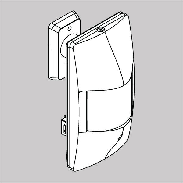
1 | x1 Sensor with x1 wall holder | |
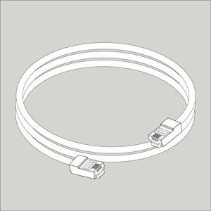
2 | RJ11 6P4C 2m cable | |
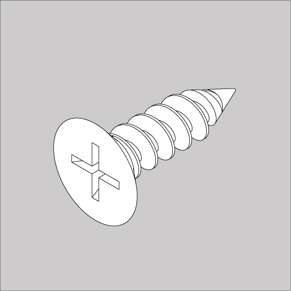
3 | x2pcs M3.5 L17.5mm countersink screws |
Settings up CAN
Copyright:
Vutlan s.r.o. (LLC)
Remote Infrastructure Monitoring and Control
43 ul.Svornosti, 821 06 Bratislava,
Slovak Republic
.jpg?version=3&modificationDate=1687181075575&cacheVersion=1&api=v2)
.jpg?version=2&modificationDate=1687181067934&cacheVersion=1&api=v2)
.jpg?version=2&modificationDate=1687181085695&cacheVersion=1&api=v2)


