...
Physical description
...
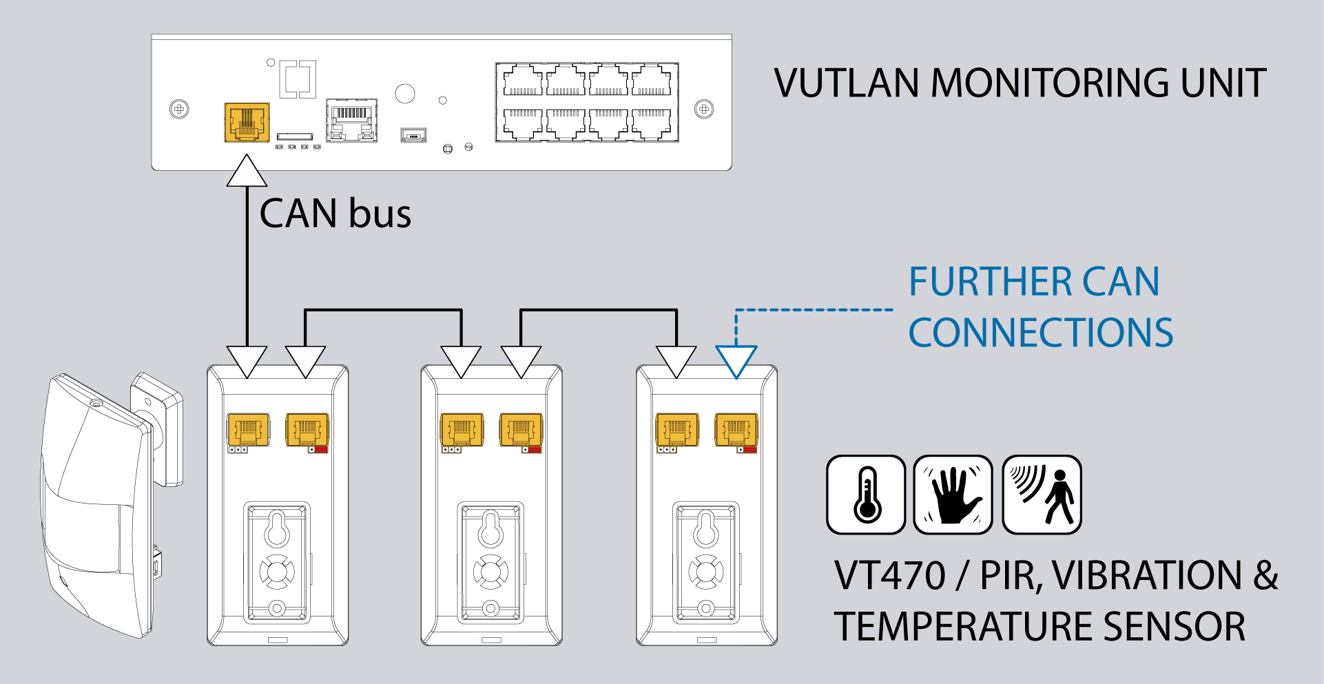
1. "CAN" - two equivalent digital RJ12 connectors for connecting CAN sensors and CAN extensions to a common bus, with auto-sensing.
2. Sensitivity (see instructions in a section below)
3. "Wall holder" - attachment place
4. "TR" - CAN bus terminator.
5. "Christal window"
6. Indicators Indicators: "Green" - shows the status "connected" to the main module, "Red" - shows the status "not connected", and "Orange" - shows the status of "Alarm".
7 "Wall holder" - supplied together with the sensor.
Product page
See more at on VT470 product page
Connecting the sensor
The sensor can be connected in a CAN chain with other CAN sensors.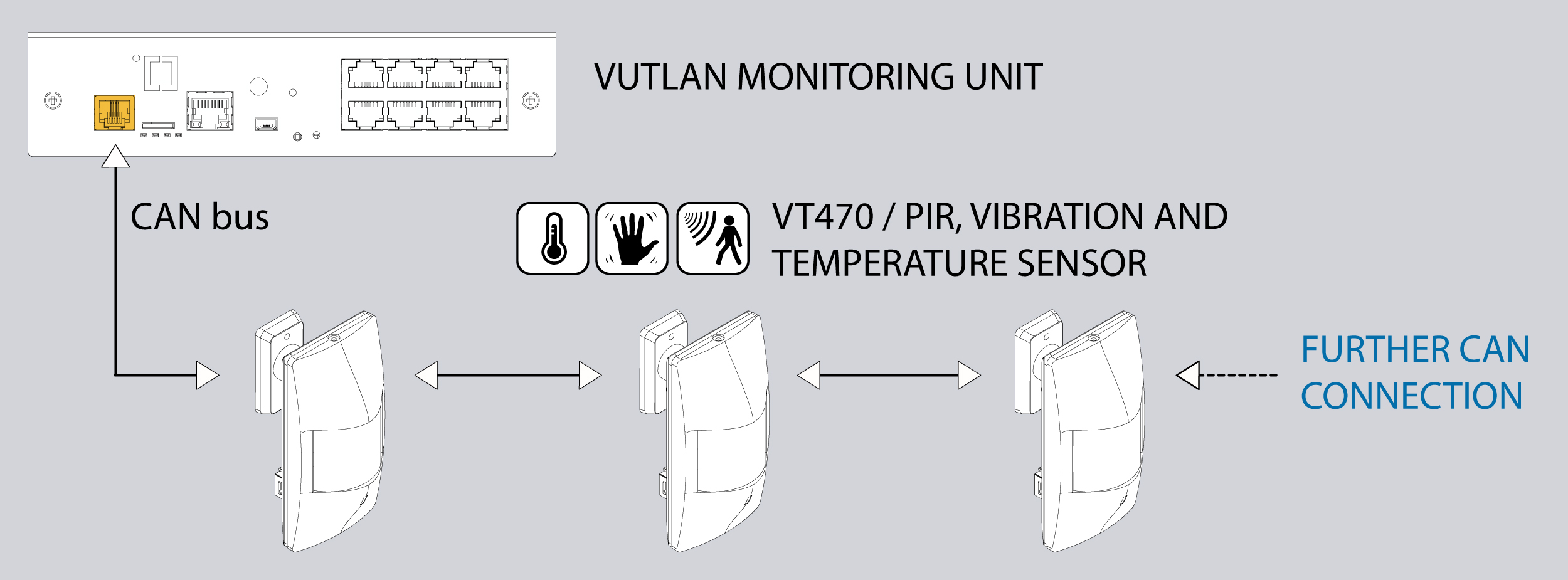
...
...
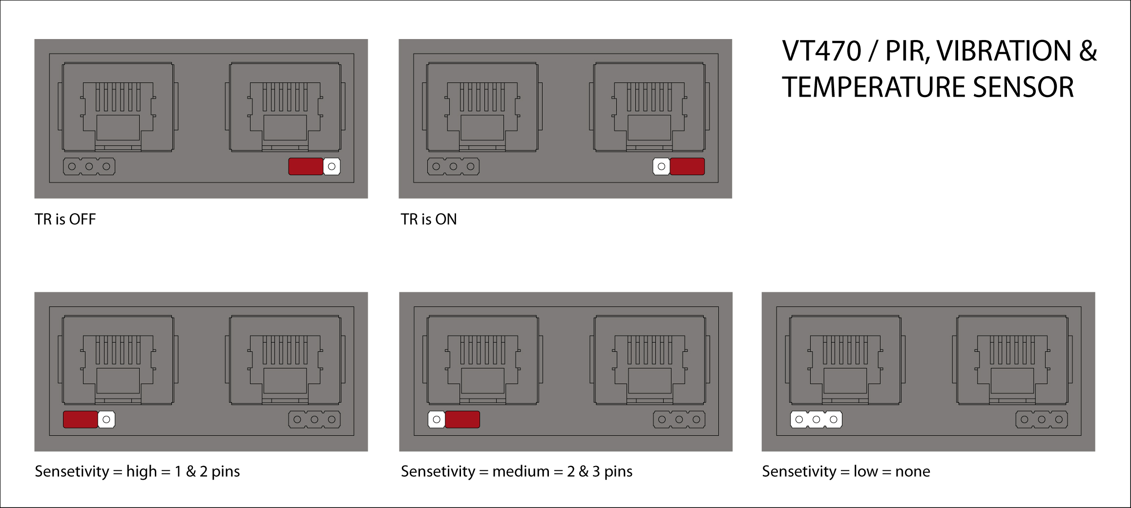

TR is OFF. Used if the sensor is not the last sensor in a CAN chain.
TR is ON. Used if the sensor is the last sensor in the CAN chain.
VT470 package content
| Include Page | ||||
|---|---|---|---|---|
|
Settings up CAN
| Include Page | ||
|---|---|---|
|
...
|
VT470 package content
...
Read more at VT470 package contentCopyright:
Vutlan s.r.o. (LLC)
Remote Infrastructure Monitoring and Control
43 ul.Svornosti, 821 06 Bratislava,
Slovak Republic