...
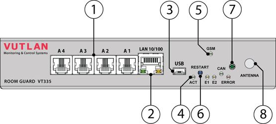
1. "A1..A4" - 4 RJ12 analog sensor inputs with auto-sensing.
2. "LAN" - Ethernet 10/100 Base-T port, provides an Ethernet connection.
• LEDs - "yellow" (status) and "green" (traffic) shows show the network traffic. The status LED: flashes green when the system starts up, and shows the connection state (constant green light - the connection is established, blinking green - the connection attempt).
...
4. LEDs: "ACT" - indicates appliance status, "E1" - indicates 12V E1 relay status, "E2" - indicates 12V E2 relay status, "ERROR»" - indicates error and traffic.
...
7. "TEMPERATURE SENSOR" - accuracy +/- 1 °C°C.
8. "ANTENNA" - connector, used when GSM modem is installed inside of the appliance to connect GSM antenna. (GSM modem is ordered separately)
9. "
 " - External chassis grounding, M4 thread.
...
11. "OUTPUT 12V 0.25A" - 12V 0.25A output electronic relay teminalterminal
12. "DRY CONTACTS 1...4" - Dry contacts terminal (type IN)
...
15. "1-WIRE" - can be used with with VT10 / 1-Wire extension board". Allows to connect 1-Wire reader or 1-Wire temperature sensors in serial line. Has "1-WIRE" status led.
16. "SIM" - connector with an ejector, with the installed and mounted GSM modem is used to connect the SIM card.
Developer notes: metal case VT335 v1.2