...
...
Connection diagram
All monitoring units, VT8101, VT8101T, VT8110, VT800, VT808, and VT1908 have the possibility to install a GSM modem. The device is mounted and connected to the master unit. Needed when the network is absent or for reservation of a connection channel of the master unit with the Internet; for sending SMS notifications and SMS commands.
...
Supply includes
№ | Component | Description | ||||
|---|---|---|---|---|---|---|
1 |
| Modem board | ||||
2 |
| Antenna | ||||
3 |
| Antenna wire | ||||
4 |
| BH16 cable | ||||
5 |
| M3*5mm bolts. 3pcs |
Installation of GSM modem
| Note |
|---|
To install and to connect extension units: switch off appliance, unplug from the outlet or disconnect the power connector. |
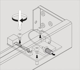
1 |
 | Carefully unscrew three screws holding the cover and open it.
| ||
2 |
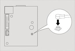
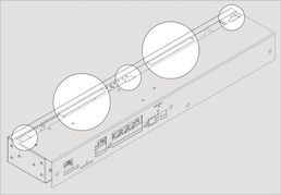
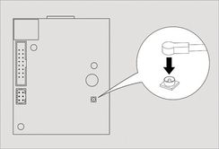 | Connect antenna cable to the modem board. Carefully connect the U-Fl antenna cable to the input U-FL connector and gently press it. If possible install the connector on the seat with a magnifying glass! |
3 |
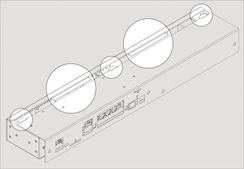
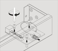 | Set up the GSM modem card on 3 steel spacing sleeves on the cover, attach card to the sleeves using three M3 screws supplied with the modem. |
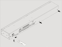
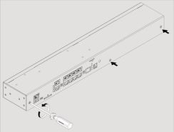
4 |
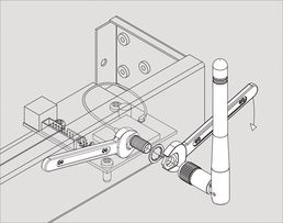
 | Set the SMA connector antenna cable to the rear or to the front panel of the appliance into the corresponding SMA hole. Put on the SMA connector gold-plated washer and nut from the supply, holding SMA connector with one key, securely tighten the nut with the other key.
| ||
5 |
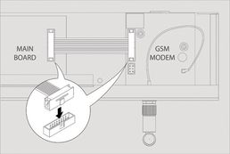
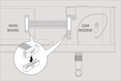 | Connect 16-pin flat cable to the connectors on the modem card and on the appliance motherboard. Close and fasten the cover. If necessary, install the SIM card into the appropriate hole. |
6 |
 | Carefully place top cover back so that all cover wings fit in and all cutoffpoints match the panel holes. Then use 3 screws to close the enclosure. When installing the green dry contact connectors can go tight, check the burrs and remove them with rasp! |