Наименование в номенклатуре изделий Vutlan и функциональные особенности распределителей электропитания (PDUNaming in the Vutlan product range and the functional features of the power distribution units (PDUs):
| Наименование | Функциональные особенности |
|---|---|
| VT11xx | PDU |
| with switching capability on each outlet | |
| VT18xx | PDU |
| with measurement capability on each outlet | |
| VT19xx | PDU |
...
| with the ability to measure and switch on each outlet |
, where xx are possible executions:
| Кол-во модулей PDU | Исполнение, xx | Описание |
|---|---|---|
| 1 | 08 | 8 |
| channels ( |
| outlets) | ||
| 2 | 16 | 16 |
| channels ( |
| outlets) | ||
| 3 | 24 | 24 |
| channels ( |
Среди параметров различают общие параметры модулей и параметры каналов.
Параметры измерительного модуля подробно описаны в соответствующем разделе.
Состояние модуля PDU характеризуется следующей таблицей:
Напряжение, V
Частота, Hz
| outlets) |
Among the parameters, the general parameters of the modules and the parameters of the channels are distinguished.
The parameters of the measuring module are described in detail in the corresponding section.
The status of the PDU is characterized by the following table:
| General parameters of the module: | ||||||||
Voltage, V | Frequency, Hz | Total active power, W | ||||||
| Channel parameters: | ||||||||
| Port number | Socket status | Current consumption, A | Active power, W | Reactive power, VAR | Total power,VA | Cosine phi,% | Current overload | Total energy consumption, Wh |
|---|---|---|---|---|---|---|---|---|
| 1 | ||||||||
| 2 | ||||||||
| .. | ||||||||
| 8 | ||||||||
Запрос состояния модуля PDU module status request:
- querytype - тип запроса: ctlmodule — управление модулемrequest type: ctlmodule - module control;
- k - идентификатор сессииsession identifier;
- id - уникальный идентификатор модуляunique identifier of the module;
- func - функция управленияcontrol function: eparams - запрос энергетических параметров;
...
- request for energy parameters;
An example of the structure of the xml response to a query:
| Code Block | ||||||
|---|---|---|---|---|---|---|
| ||||||
<!-- атрибуты модуля --> <module id="2013" clas="internal" type="outlet" sn="24663586" rev="00.09" num="1" name="Outlets bank A" state="normal" interval="0" relval="131" real_relval="0"> <!-- общие параметры --> <common col1="Voltage, W" col2="Frequency, Hz" col3="Total Power, W"> <eparam num="1" id="203002" name="BankA-General-V" state="low alarm" value="97.5" /> <eparam num="2" id="210001" name="BankA-General-F" state="normal" value="50.2" /> <eparam num="3" id="208001" name="BankA-General-Psum" state="normal" value="868.0" /> </common> <!-- таблица розеток --> <outlets col1="Outlet" col2="Current" col3="Owerload" col4="Active Power, W" col5="Reactive power, VAR" col6="Apparent power, VA" col7="Cos Fi, %" col8="Crest factor" col9="Total energy consumption Wh"> <outlet hwport="1"> <eparam num="1" id="302001" name="Outlet-1" state="on" /> <eparam num="2" id="205001" name="Outlet-1-I" state="normal" value="8.925" /> <eparam num="3" id="109001" name="Outlet-1-OVERLOAD" state="normal" /> <eparam num="4" id="208002" name="Outlet-1-P" state="normal" value="868.0" /> <eparam num="5" id="208003" name="Outlet-1-Q1" state="low alarm" value="71.0" /> <eparam num="6" id="208004" name="Outlet-1-S" state="normal" value="876.0" /> <eparam num="7" id="209001" name="Outlet-1-Cos" state="high alarm" value="1.0" /> <eparam num="8" id="209002" name="Outlet-1-CF" state="high alarm" value="2.0" /> <eparam num="9" id="208005" name="Outlet-1-PC" state="normal" value="553.0" /> </outlet> <outlet hwport="2"> <eparam num="1" id="302002" name="Outlet-2" state="off" /> <eparam num="2" id="205002" name="Outlet-2-I" state="low alarm" value="0" /> <eparam num="3" id="109002" name="Outlet-2-OVERLOAD" state="normal" /> <eparam num="4" id="208006" name="Outlet-2-P" state="low alarm" value="0.0" /> <eparam num="5" id="208007" name="Outlet-2-Q1" state="low alarm" value="0.0" /> <eparam num="6" id="208008" name="Outlet-2-S" state="low alarm" value="0.0" /> <eparam num="7" id="209003" name="Outlet-2-Cos" state="high alarm" value="0.0" /> <eparam num="8" id="209004" name="Outlet-2-CF" state="high alarm" value="0.0" /> <eparam num="9" id="208009" name="Outlet-2-PC" state="low alarm" value="0.0" /> </outlet> ... и так далее </outlets> </module> |
Макет панели
Макет панели управления PDU с возможностью измерения и коммутации на каждой розетке: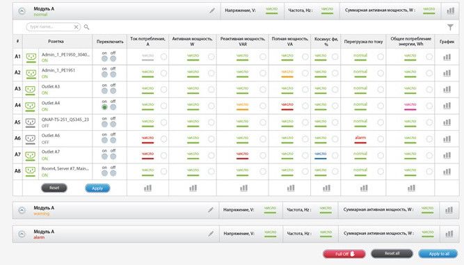
Панель должна обеспечивать настройку свойств модуля при помощи пиктограммы "карандаш".
Панель должна обеспечивать поиск или фильтр каналов (строк) модуля по имени, порту и состоянию параметра (элемента).
Панель должна обеспечивать настройку параметров (элементов) модуля. Параметры представляют собой элементы:
- розетки - элемент класса переключатель, быстрое управление состоянием (on/off) произодится при помощи RadioBox в столбце "Переключить", детальное упраление (имя, состояние и т.п.) производится при помощи стандартной формы управления розеткой по клику на имени розетки в столбце "Розетка"
- перегрузка по току - элемент с дискретным выходом, управление (имя и т.п.) производится при помощи стандартной формы управления дискретным элементом по клику на имени параметра (или ячейке таблицы?) в соответствующем столбце;
- элементы с аналоговым выходом: все остальные, управление (имя, уровни срабатывания и т.п.) производится при помощи стандартной формы управления аналоговым элементом по клику на имени параметра (или ячейке таблицы?) в соответствующем столбце;
Панель должна обеспечивать:
- сброс в off управления состоянием всех розеток для модуля (кнопка "Reset") и для всех модулей (Кнопка "Reset All");
- применение управления всеми розетками для модуля (кнопка "Apply") и для всех модулей (Кнопка "Apply All");
- быстрое полное отключение всех розеток всех модулей с защитой паролем (может ограничится только предупреждением, без пароля? в противном случае неоперативно);
Панель должна позволять строить графики:
...
...
Layout of the panel
The layout of the control panel PDU with the possibility of measuring and switching on each outlet:
The panel should provide setting of properties of the module by means of the icon "pencil".
The panel should provide search or filter channels (lines) of the module by name, port and state of the parameter (element).
The panel must provide configuration for the parameters (elements) of the module. Parameters are the elements:
- sockets - a switch class element, fast state control (on / off) is performed using the RadioBox in the "Switch" column, detailed control (name, status, etc.) is performed using the standard socket control form by clicking on the socket name in the column "Power socket"
- current overload - an element with a discrete output, control (name, etc.) is performed using the standard control form of discrete element by clicking on the parameter name (or the cell of the table?) in the corresponding column;
- elements with analog output: all the other, control (name, trigger levels, etc.) is performed using the standard form of controlling the analog element by clicking on the parameter name (or the cell of the table?) in the corresponding column;
The panel should provide:
- reset control to "Off" state of the status of all outlets for the module ("Reset" button) and for all modules ("Reset All" button);
- application of control of all outlets for the module ("Apply" button) and for all modules ("Apply All" button);
- rapid full shutdown of all outlets of all modules with password protection (can be limited only by warning, without a password? otherwise, non-operative);
The panel should allow you to build graphs:
- for mutual parameters of one module (voltage, frequency, total active power), the graph panel is called up by means of a button at the end of the general parameters line;
- for the parameters of one channel in one module, with the necessary parameters in the line selected using RadioBox, calling the chart panel using the button at the end of the channel parameters
- for several identical parameters of different channels of the same module, with the necessary parameters in the column selected using RadioBox, calling the chart panel is made using the button at the bottom of the column;