Product page: VT520DIN / AC voltage monitor
Description


Function
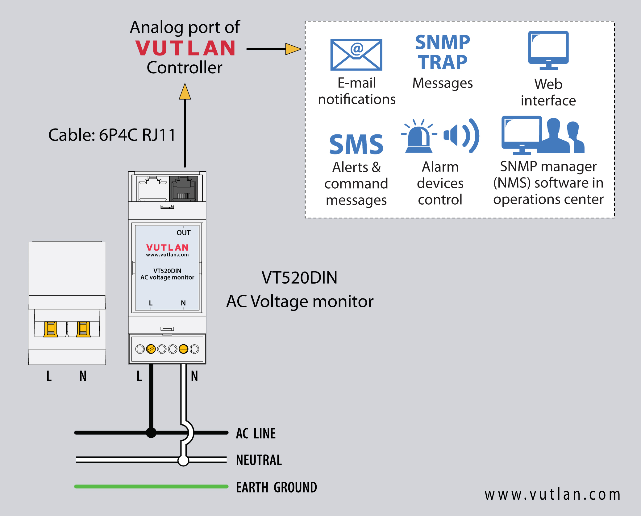
AC analog voltmeter (a.k.a. sensor, voltage monitor, voltage meter) is needed for the measurement of AC 0-246V. It has a high accuracy of 1%. The device can be monitored using any of Vutlan's monitoring systems, which can be set up to notify and control the equipment in case of an emergency.
Technical specifications
The technical specification can be found on the product page VT520DIN
Components
The sensor consists of
- DIN rail 2M plastic housing: flammability rating is UL94V-0; body color is grey; the material is ABS
- AC voltage meter board

| Include Page | ||||
|---|---|---|---|---|
|
Safety instructions
Carefully READ and FOLLOW the safety precautions outlined below BEFORE working with the voltmeter.
- Only qualified electrical workers should install this equipment. Such work should be performed only after reading this entire set of instructions.
- NEVER work alone.
- Before performing visual inspections, tests, or maintenance on this equipment, disconnect all sources of electric power. Assume that all circuits are live until they have been completely de-energized, tested, and tagged. Pay particular attention to the design of the power system. Consider all sources of power, including the possibility of back feeding.
- Turn off all power supplying the voltmeter and the equipment in which it is installed before working on it.
- Always use a properly rated voltage-sensing device to confirm that all power is off.
- Apply appropriate personal protective equipment (PPE) and follow safe electrical work practices. In the USA, see NFPA 70E
- Before closing all covers and doors, carefully inspect the work area for tools and objects that may have been left inside the equipment.
- Use caution while removing or installing panels so that they do not extend into the energized bus; avoid handling the panels, which could cause personal injury.
- The successful operation of this equipment depends upon proper handling, installation, and operation. Neglecting fundamental installation requirements may lead to personal injury as well as damage to electrical equipment or other property.
- The power meter should be installed in a suitable electrical and fire enclosure.
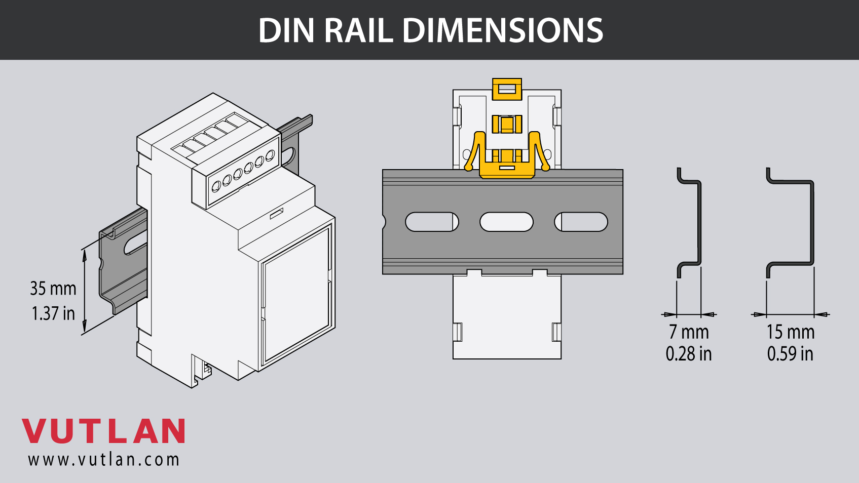
Dimensions

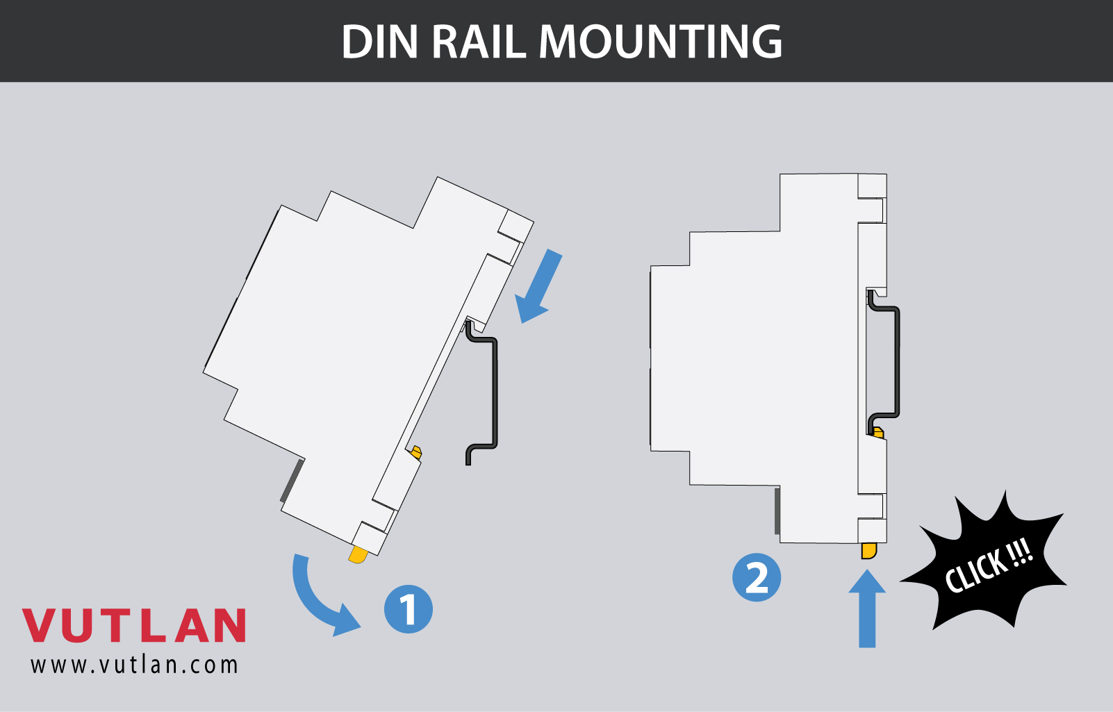
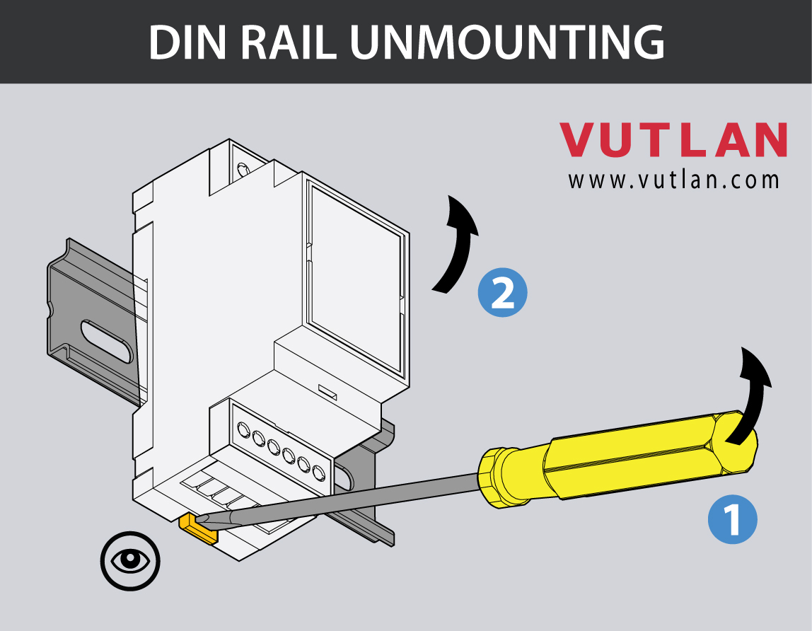
Mounting
1. The device is mounted onto a DIN rail 35mm bar.
2. Insert the wall clip / DIN rail clip into the enclosure.
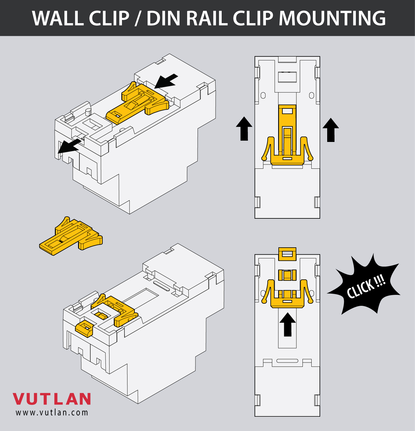
3. Insert/press the enclosure onto the DIN rail bar.
4. In case You need to unmount it, pull the wall clip / DIN rail guard with the screwdriver and pull the enclosure outwards.
Wiring
1. Switch OFF the power of the AC line and follow other instructions from the section "Safety instructions".
5. Follow power cable specifications for the next step.
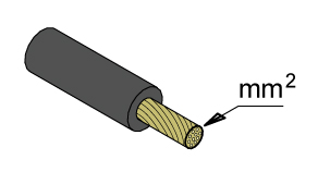
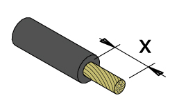
Specifications | Strip length | Wire cross-section | Screw head | |
|---|---|---|---|---|
|  |  | ||
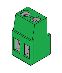
Terminal block Pins: 2P Step: 5.08 mm, 0.2 in
|  | 6 - 7 mm, 0.23 - 0.27 in | 2.5 mm², 0.09 in² #26 - #12 AWG | Flat 3.5 mm, 0.13 in |
6. Insert the power cables.
| Warning |
|---|
Make sure You follow "Safety instructions" at the beginning of the instruction. |

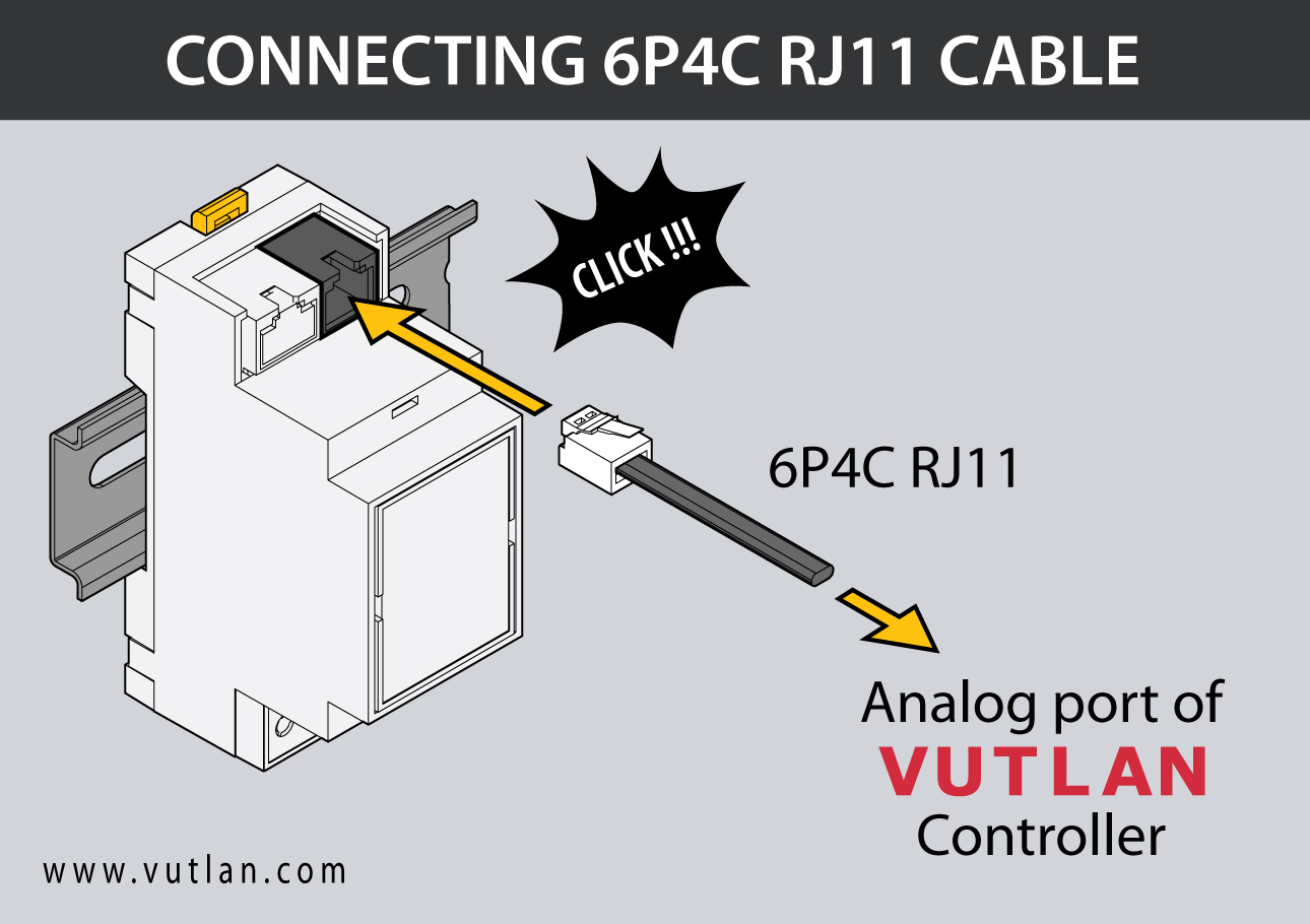
7. Connect the device with the Vutlan monitoring system using a 6P4C RJ11 cable (cable is supplied).
9. Turn the AC line power back ON.
| Include Page | ||||
|---|---|---|---|---|
|
Connection wiring/cable pinouts
Cable 6P4C RJ11
Used for connecting the device with
The transducer and the transceiver are installed together.
- Mount the transducer using M4 screws and M4 nuts. The distance between mounting holes is 50 mm.
- Mount the current transceiver using M4 screws and M4 nuts. The distance between mounting holes is 60 mm.
- Use a 4-core flat cable and two green connectors supplied with the transceiver and the transducer to assemble the connecting cable.
| Include Page | ||||
|---|---|---|---|---|
|
Technical support
The device does not contain any user-serviceable parts. If the power meter requires service, contact your local sales representative. Do not open the device. Opening the device voids the warranty.
Troubleshooting
The following table describes potential problems and their possible causes. It also describes checks you can perform or possible solutions for each. After referring to this table, if you cannot resolve the problem, contact your local Vutlan sales representative for assistance.
| Potential Problem | Possible Cause | Possible Solution |
|---|---|---|
| The data being displayed is inaccurate or not what you expect. | Incorrect setup values. | Check that You use the correct f(x) formula |
| Incorrect voltage inputs. | Check power meter voltage input terminals to verify that adequate voltage is present | |
| The power meter is wired improperly. | Check that all wires are connected correctly and that they are energized. See “Wiring Diagrams” of the device. | |
| The sensor does not appear in the Vutlan monitoring interface | Communications lines are improperly connected. | Check the 6P4C RJ11 communication cable. |
| The communication cable is inserted into the wrong port. | 6P4C RJ11 communication cable must be inserted into the analog port of the Vutlan monitoring system. |
Frequently asked questions
| Question | Answer |
|---|---|
| What is max A for VT520 and VT520DIN? | There are no ampers through VT520/VT520DIN. It has a 140K resistor on the input. |
| ... |