...
The Modbus operates in "Master" mode. To enable the Modbus, go inside the web interface of Vutlan monitoring unit and go to Preferences menu >> Modbus RTU. Set up the bus according to the documentation for the "Slave" equipment.

Please note "VT85 / Modbus extension board" only support 1 stop bit.
 Adding the Modbus virtual element
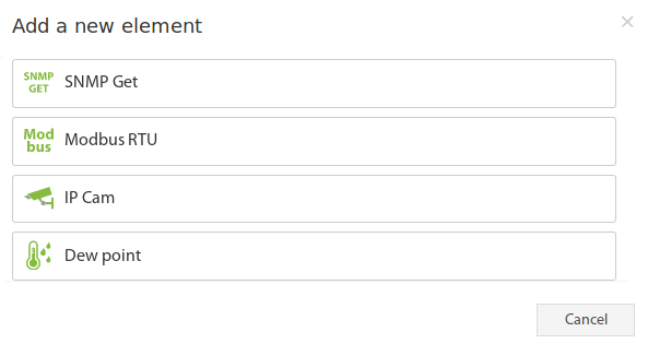
To create a "Modbus RTU" element, press add button "  " inside "Group tree" or "System tree" menu. Then choose "Modbus RTU". A modal window will appear:

Click on the "Modbus RTU". Modbus element form will be opened:


Fields in the form available for change:
...
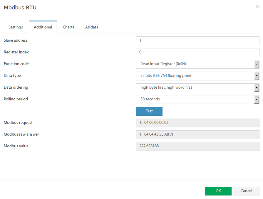
The Modbus RTU bus configuration available in "Additional" tab:
...
Fields in the form available for change:
| # | Name | Description |
|---|---|---|
| 1 | Slave address | Modbus RTU slave address of external equipment |
| 2 | Register index | Modbus protocol register start addres in hexademal view, like 0046 |
| 3 | Function code | The following functions are supported:
|
| 4 | Data type | Determines how to present the data:
|
| 5 | Data ordering | Determines byte order in Modbus protocol response message:
|
The Test button allows you to make a test connection with a modbus device. In additional fields, the bytes sequence of connection data is displayed, in hexadecimal form. Modbus request - data of the sent request, without a checksum. Modbus raw answer - data of the received answer, without a checksum. Modbus value - contains the data value interpreted in accordance with the selected Data type.
Example, adding input register "Active power" for Eastron SDM220 Modbus slave
...
Press add button " " inside "Group tree" or "System tree" menu. Then choose "Modbus RTU". A Modbus element form will be opened:


Let's change values in Setting tab:
...
Now let's change the values in Additional settings tab tab:

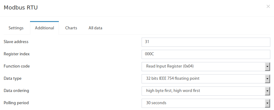
| # | Name | Description |
|---|---|---|
| 1 | Slave address | on page 2 of SDM220ModbusEN.pdf it is stated in the table in row 16 that: "How to find Modbus address. By default it is 001" But in our case it is different, a slave address has been manually altered. So,after following the procedure and navigating to slave address onscreen instruction, we find out that the Salve address for this device is currently set to 31 in our example. It is advised to have have a slave address according to position in a Modbus chain. So if the sensor is currently 1st in a Modbus chain, set it to 1. So we write 31. |
| 2 | Register index | on page 2 of SDM220Modbus_protocol_V1.1.pdf it is stated in the table that: "Hi Byte = 00 + Lo Byte = 0C" |
| 3 | Function code | on page 2 of SDM220Modbus_protocol_V1.1.pdf it is stated that: "Modbus Protocol function code 04 is used to access all parameters." So we write: 0x04 - Read Input Registers |
| 4 | Data type | on page 1 of SDM220Modbus_protocol_V1.1.pdf it is stated that: "The format for each byte in RTU mode is: Coding System: 8-bit per byte Data Format: 4 bytes (2 registers) per parameter. Floating point format ( to IEEE 754)" or on page 2 it is stated that: "the data used by the Eastron Digital meter is in 32 bit IEEE 754 floating point format." So we write: 32 bits IEEE 754 floating point |
| 5 | Data ordering | on page 1 of SDM220Modbus_protocol_V1.1.pdf it is stated that: "Most significant register first (Default). The default may be changed if required -See Holding Register "Register Order" parameter." So we write: low byte first, low word first |
...