...
| Warning |
|---|
The sensor is developed and tested. Ready for sale. But this article is currently being written, some of the information in this article may be incorrect. |
Functional description & components
Physical description
...
![]()
Dimensions

![]()
Function
The "VT417 / AC Ampere meter" together with the current transformer allows measuring the alternating current.
By default, the converter is equipped with a current transformer that allows measuring alternating current in the range of 0.01 ... 16A20A.
![]()
| Info |
|---|
Supply of Ampere meter with different parameters (from 0.01 to 100 Amperes) is possible on request. Sensor has a possibility to have 25mA or 50mA as an output. |
...
Inventory / components
The Ampere meter consists of RMS-to-DC converter and a current transformer. They are connected using two wire connection and 2P 5.08mm terminal. The converter is connected to the main monitoring unit using RJ11 6P4C telephone cable.
| Include Page | ||||
|---|---|---|---|---|
|
Safety instructions
- Please observe the valid regulations for installation in the country in which current meter is installed and operated, and the national regulations for accident prevention. Please also observe any internal company regulations, such as work, operating and safety regulations.
- The technical specifications and limit values stated must not be exceeded under any circumstances. In particular, this applies to the specified ambient temperature range and IP protection category.
Siting location requirements
To ensure proper functionality, the conditions specified in section “Technical specifications” must be observed.
Installation procedure
Notes on assembly
- Be careful, transducers max. voltage for isolation is 2kV.
- The transducer can measure AC current on any current wire, not more then 10 6 mm in diameter. Just open the cover, insert the wire and close.
- Max. distance for AC current transducer Ampere meter from monitoring unit is 50 meters.
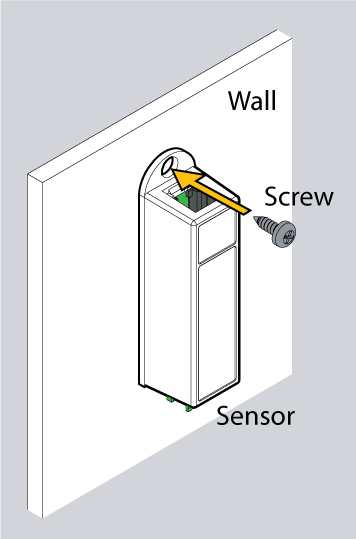
Mounting
Mount the converter by:
a) Sticking it to the wall using the sticker
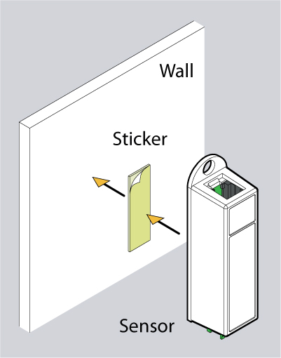
or by
b) Screwing it to the wall
Installation
![]()
The transducer and the transceiver installed together.
- Mount transducer using M4 screws and M4 nuts. Distance between mounting holes is 50 mm.
- Mount current transceiver using M4 screws and M4 nuts. Distance between mounting holes is 60 mm.
- Use a 4-core flat cable and two green connectors supplied with the transceiver and the transducer to assemble the connecting cable.
Connection
Connect one end of RJ11 / RJ12 cable to monitoring unit and the other end to analog output of transceiver. Connect transceiver to power adapter 12V. Connect transceiver and transducer with Connecting cable. The monitoring system will automatically sense current transducer as a sensor.
...
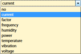
- Change type of the sensor by choosing "Current". Choosing any type of the sensor does not affect sensor properties, it only changes sensor icon for comfort of usage.
- Change the name of sensor, for example "AC current".
- Use "Expression formula": 20*x, where K=20.
- Put in the threshold levels by dragging: Low alarm, Low warning, High warning, High alarm levels.

For example, graph above shows that the state of the sensor at the moment is "Normal" because 20.4 is between "Low warning" and "High warning" states, which is considered "Normal" state. - Click “Save” or “Apply” at the bottom of the “Properties” window. The page will reload and the sensor will update by changing it's icon type to
 (abreviation from: "Ampers").
Manipulating transducers
| Warning |
|---|
Do not tweak transducer's variable resistors. They are tweaked by the manufacturer for optimal measurement. Tweaking these may result in incorrect measurement. |
Technical specifications
HAT-100Q1 / AC current transducer | |
|---|---|
| Dimensions | Size 60 × 61 × 16 mm |
| Weight | 150 g |
| Operating temperature | Temperature : Min. -10° C - Max.80° C |
| Operating humidity | Min. 5% - Max. 95% (Non-Condensing) |
| Power input | -12V / +12V |
| Outputs | 4 pin terminal |
| Mounting | Wall mount |
| Power Consumption | 1 Watt |
| Max. distance m | 50 m |
| HS Code | 9030 33 100 |
Usage examples
Example 1: Using logic to turn on equipment & monitor it's status

Example 2: Switch off equipment before it overloads

Equipment life prediction

Notify personnel if jam occurs

Developer zone link: Transformator RMS-to-DC VT417