...
Datasheet page: https://vutlan.atlassian.net/l/cp/FxCBogKP
The sensor must be used together with
(recommended) (ordered separately) |
|---|
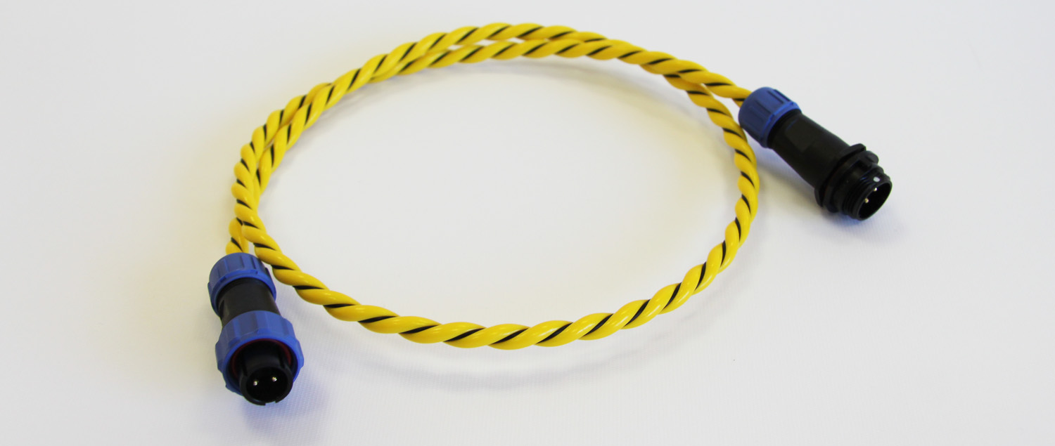
"WLC / Water leak cable" is ordered separately! When water is in contact with the detection cable sensor indicates the emergence of moisture. The whole area can be effectively monitored by placing the cable near or along with possible flood sources.
...
Usage examples
...
Technical specifications
VT591 / Water leak sensor specifications | |
|---|---|
Dimensions | 60×18×18 mm |
Weight | 60 g |
Input | 2 wire (WDC cable) |
Output | RJ11 / RJ12 (6p4c) |
Operating temperature | -10 °C to +80 °C |
Operating humidity | 5% to 95% (Non-Condensing) |
Mounting | Mounting bracket included. |
Power consumption | 60mW |
Max. distance m | 100 m |
HS Code | 9025 80 400 |
Components | Manufactured in E.U. |
Special features | Response time: 15 sec., Recovery time: Depends on how fast the sensor dries out |
WLC / Water leak cable specifications | |
|---|---|
Description | WLC can work in high humidity, pollution, and hazardous waste |
Detectable liquids | Clean, polluted & distilled water; acids; alkalis; alcohols, and other electrically conductive liquid |
Diameter | 5.5 mm in diameter |
Lengths | Order options include 10m, 15m, 25m, 50m, or custom length. |
Weight | 26 g/m |
Operating humidity | 0° - 95 % |
Max. cable length | 225 m |
Inputs | x2 wires |
Package content
| Include Page | ||||
|---|---|---|---|---|
|
Connecting WLC / Water leak cable
...
Please find installation examples in our articles "Water leakage detection using cable sensor and spot sensor" and "Leak detection under raised floors in data centers".
Cable layouts
Cover the whole area Comprehensive protection for critical areas | |
Cover the edge area Prevent leaks from immersing in or spreading out | |
Covering air-conditioned areas Key protection against major leakage sources such as alr conditioners |
Cable pinouts
The sensor uses a standard Vutlan analog sensor cable(RJ11/RJ12 to RJ11/RJ12) for connecting to the monitoring unit. You can find further instructions at the Analog sensors connection
...
The device does not contain any user-serviceable parts. If the power meter requires service, contact your local sales representative. Do not open the device. Opening the device voids the warranty.
Schematics / Sensitivity adjustment
You can change the R10 resistor using the following schemes.
...
The following table describes potential problems and their possible causes. It also describes checks you can perform or possible solutions for each. After referring to this table, if you cannot resolve the problem, contact your local Vutlan sales representative for assistance.
Potential Problem | Possible Cause | Possible Solution |
|---|---|---|
The data being displayed is inaccurate or not what you expect. | Incorrect setup values. | Check that You use the correct f(x) formula |
Incorrect voltage inputs. | Check power meter voltage input terminals to verify that adequate voltage is present | |
The power meter is wired improperly. | Check that all wires are connected correctly and that they are energized. See “Wiring Diagrams” of the device. | |
The sensor does not appear in the Vutlan monitoring interface | Communication lines are improperly connected. | Check the 6P4C RJ11 communication cable. |
The communication cable is inserted into the wrong port. | 6P4C RJ11 communication cable must be inserted into the analog port of the Vutlan monitoring system. | |
The sensor is always in alarm state. | The cable touches itself. | The cable can not touch itself. It needs to be straightened. Please check if the cable is bent anywhere. |
The cable is twisted or pressed down too much. | Do not twist or press down the cable too much. This may lead to deformation. The cable has two sensing wires, these wires can not touch each other. | |
The cable is located on a conductive surface. | Do not put the cable on a conductive surface. | |
The cable is damaged | Check the continuity of the cables with a multimeter. Let’s call each wire A and B: If the cable is not damaged, you should get the following results
If the cable is damaged, you will get:
or
|
...
Copyright:
Vutlan s.r.o. (LLC)
...
.png?version=1&modificationDate=1559827911666&cacheVersion=1&api=v2)
.png?version=1&modificationDate=1559827913876&cacheVersion=1&api=v2)


