...
Virtual "Modbus RTU" sensor is used to read and write data from external equipment via Modbus RTU protocol (RS-485 line). An external converter to the USB bus is used to provide RS-485 communication.
...
The Modbus operates in "Master" mode. To enable the Modbus, go inside the web interface of Vutlan monitoring unit and go to Preferences menu >> Modbus RTU. Set up the bus according to the documentation for the "Slave" equipment. Please note "VT85 / Modbus extension board" only support 1 stop bit.

Adding the Modbus reading virtual element
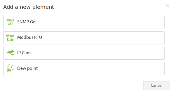
To create a "Modbus RTU (reading)" element, press add button "  " inside "Group tree" or "System tree" menu. Then choose "Modbus RTU (reading)". A modal window will appear:
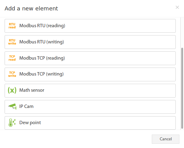
Click on the "Modbus RTU (reading)". Modbus element form will be opened:

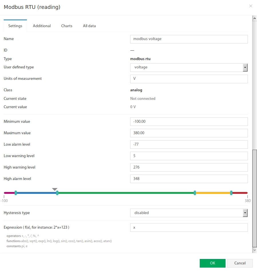
Fields in the form available for change:
...
The Modbus RTU bus configuration available in "Additional" tab:
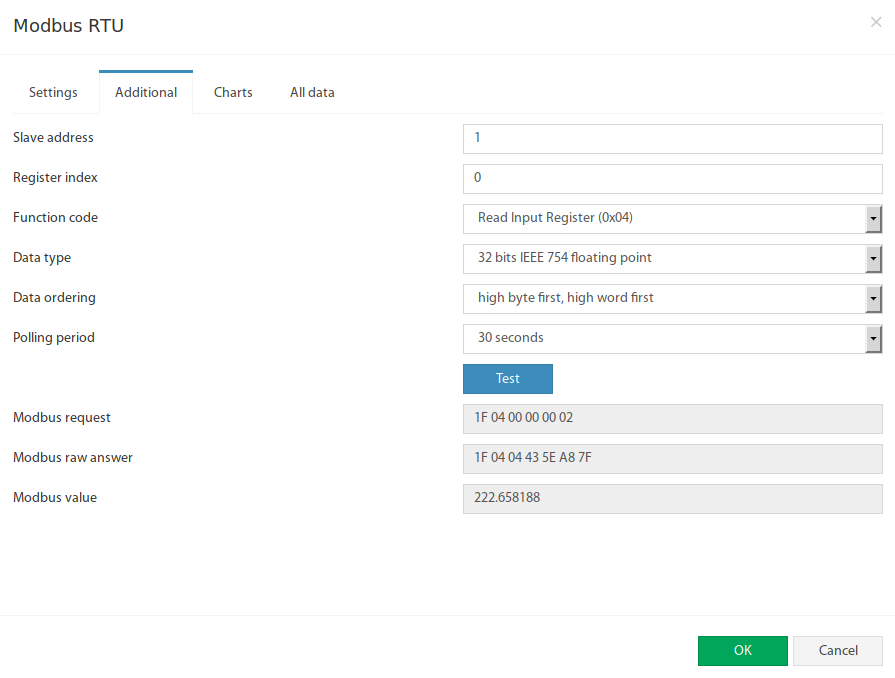
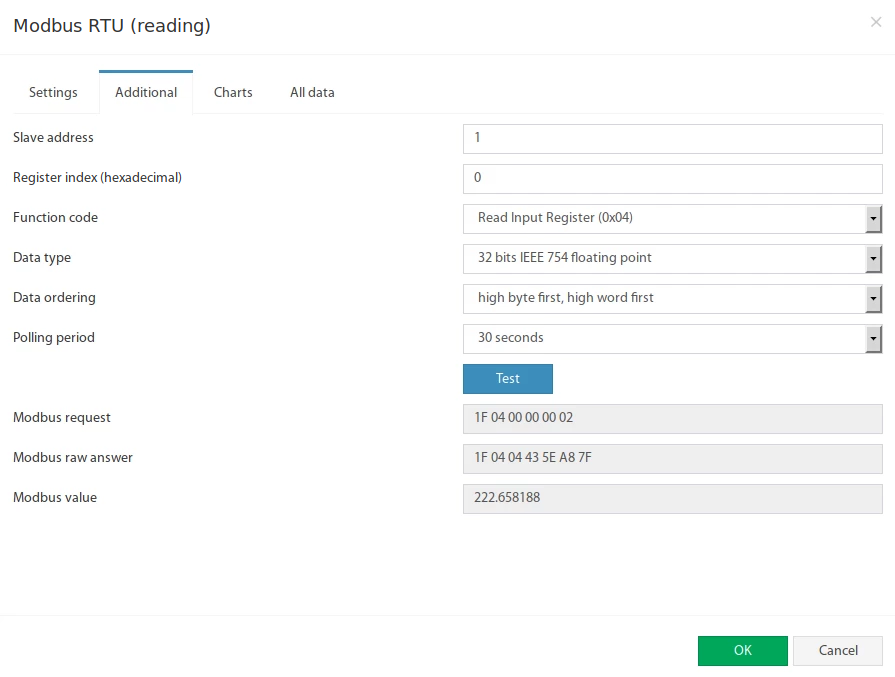 Fields in the form available for change:
| # | Name | Description |
|---|---|---|
| 1 | Slave address | Modbus RTU slave address of external equipment |
| 2 | Register index | Modbus protocol register start addres in hexademal hexadecimal view, like 00460F4A |
| 3 | Function code | The following functions are supported:
|
| 4 | Data type | Determines how to present the data:
|
| 5 | Data ordering | Determines byte order in Modbus protocol response message:
|
| 6 | Polling period | Defines the time of polling the sensor value. From 10 seconds to 5 minutes. |
The Test button allows you to make a test connection with a modbus device. In additional fields, the bytes sequence of connection data is displayed, in hexadecimal form. Modbus request - data of the sent request, without a checksum. Modbus raw answer - data of the received answer, without a checksum. Modbus value - contains the data value interpreted in accordance with the selected Data type.
Adding the Modbus writing virtual element
To create a "Modbus RTU (writing)" element, press add button " " inside "Group tree" or "System tree" menu. Then choose "Modbus RTU (writing)". Modbus element form will be opened:

Fields in the form available for change:
| # | Name | Description |
|---|---|---|
| 1 | Name | Created element name |
| 2 | Slave address | Modbus RTU slave address of external equipment |
| 3 | Register index | Modbus protocol register start addres in hexadecimal view, like 0F4A |
| 4 | Function code | The following functions are supported:
|
| 5 | Writing value | Decimal integer value that will be writing in the specified register |
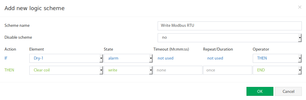
The Test button allows you to make a value entry immediately into the Modbus register. Now the Modbus RTU writing can be inserted as a THEN task in logic schemes:
Example, adding input register "Active power" for Eastron SDM220 Modbus slave
...