...
Module VT408DIN is designed to expand the number of analog sensors connected to monitoring systems.
.jpg?version=1&modificationDate=1596454571545&cacheVersion=1&api=v2&width=800)
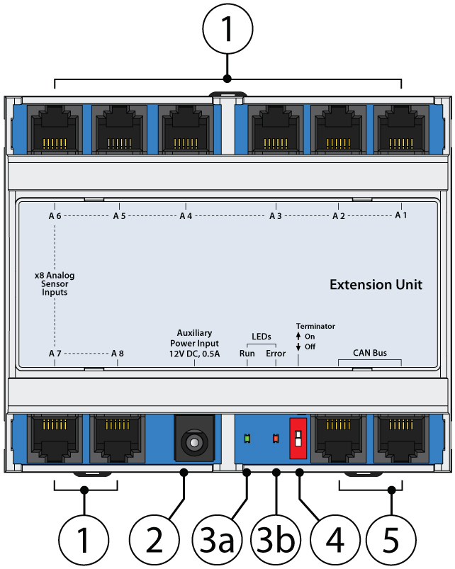
1. "A1..A8" - x8 RJ11 6P4C analog sensor input ports with auto-sensing.
...
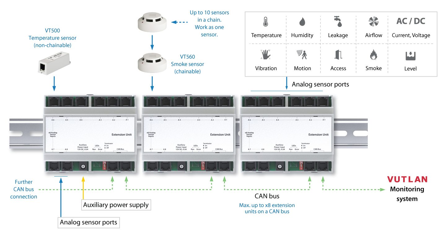
VT408DIN module is developed to expand the number of analog sensors connected to the monitoring system. The picture below illustrates the expansion example:
Mounting
...
DIN rail
...
mounting
- There are
...
- DIN rail mounting hooks at the top and the bottom of the
...
.jpg?version=1&modificationDate=1596454571545&cacheVersion=1&api=v2&height=250)
-05-06.jpg?version=1&modificationDate=1596454574125&cacheVersion=1&api=v2&height=250)
...
- case. Pull them outwards.
- Press the enclosure against the DIN rail so that it fits behind the enclosure.
- Tap the hooks back in to snap to the DIN rail.
.jpg?version=1&modificationDate=1596458306926&cacheVersion=1&api=v2&width=1000)
DIN rail unmounting
- Use a screwdriver and pull the x3 hooks on the enclosure outward.
- Pull the enclosure away from the DIN rail.
.jpg?version=1&modificationDate=1596454573210&cacheVersion=1&api=v2&width=400)
DIN rail extension, wall brackets are purchased separately.
19" mounting bracket
It is possible to use a 19inch mounting bracket to mount x3 VT408 units in one 1U rack space. 19" bracket is purchased separately.
.jpg?version=1&modificationDate=1596449632745&cacheVersion=1&api=v2&width=600)
Installation
Connect CAN input of the unit by RJ11 /RJ12 6P4C cable supplied to the CAN input of previous CAN unit or monitoring system. The red LED lights up. Match the TR bus terminators on the attached CAN units. CAN bus terminators TR (position 2 in VT450) should be in the ON state only at the end CAN units port and in Off states (1,2) for all intermediate units. One CAN bus can have not more than 8 CAN units, sensors and / or another CAN devices.
...