 End of Life: 31.10.2022

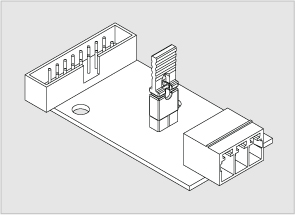
"VT85 / Modbus extension board" is used for connecting Modbus RTU devices/meters/sensors to VT325, VT335S, VT335S DC, VT805, VT825, VT825 DC monitoring systems.
For VT85 to function properly, it must be screwed in its place in the enclosure of the unit. This is because the COM line on VT85 is provided using the unit's enclosure. |
Front panel
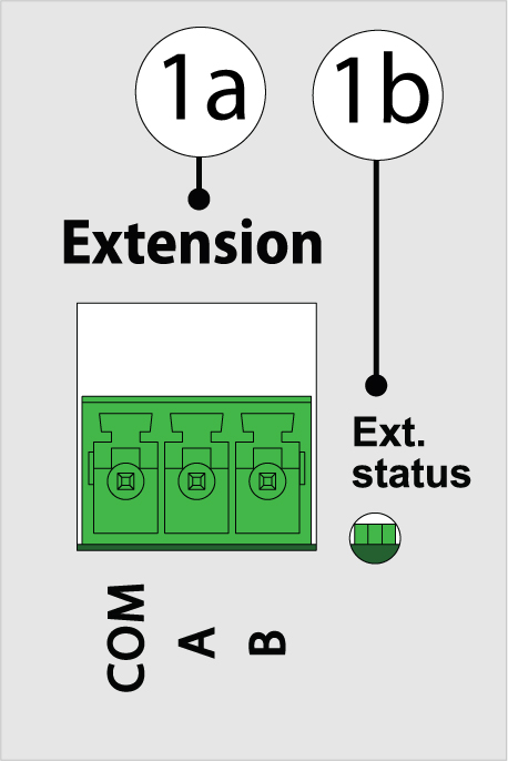
When "VT85" is installed inside of monitoring unit, "VT85" looks like this from the front panel:

- COM / A / B: three-pin Terminal 3.5 mm 3P for connecting Modbus sensors.
- Ext. status: Red LED for data transfer. Green LED for data receiving. (left to right)
Connection
The board is mounted and connected inside the monitoring unit. The expansion board has a 3 pin terminal.
To install and connect extension boards: turn off the device, remove the plug from the outlet or disconnect the power terminal. |
Only one of the extension boards can be installed: either "VT85 / Modbus extension board" or "VT10 / 1-Wire extension board". |
| 1 | | - Unscrew the bolts on the front of the unit.
|
| 2 | | - Open and lift the cover of the enclosure. Bite off the thin bridges in the hole to free space for the VT85 3P terminal. Check that there are no more left protruding parts.
|
| 3 | 
Example: VT825

Example: VT805 | - Install expansion board on 4 support in the bottom of the case, screw with two bolts.
For VT85 to function properly, it must be screwed in its place in the enclosure of the unit. This is because the COM line on VT85 is provided using the unit's enclosure. |
|
| 4 | | - Connect the "IDC16 Flat Cable" to the connector on the expansion board and the connector on the device's motherboard.
|
| 5 | | - Check if the cables are connected correctly. Carefully place the top cover of the case so that the wings on the picture do not scratch the case. Make sure that the cable and wires lying inside the device do not interfere with a cover. Make sure that the board terminals crawl through the bottom cover. Do not use force!
- Close and tighten the cover of the device.
- Connect the power plugs to the connectors.
|
Connecting Modbus RTU sensors:
Example 1: Daisy chain connection (the main controller is located at the beginning of the chain)
- Sensors are connected in a daisy chain connection.
- 120Ω resistor is used at the end of the chain which is equal to the resistance of the cable.
- A twisted pair cable is used for A(+) and B(-).
- "RS85 / Modbus extension board" has an internal termination and by default, it is switched ON. (If required possible to switch OFF)
- Up to 32 devices can be used.
- Overall cable length is no more than 1000 meters.

Example 1: Daisy chain connection (the main controller is located at the beginning of the chain)
"RS85 / Modbus extension board" has an internal termination and by default, it is switched ON. You need to lift off the jumper on the RS85 extension board to switch off the termination.
- Switch off the Vutlan monitoring unit.
- Unscrew the enclosure and lift the main cover of the enclosure.
- Find VT85 and lift the jumper.
- Close the enclosure,


Now it is possible to connect the Modbus sensors in a daisy chain with the Vutlan monitoring unit in the middle of the chain.
- Sensors are connected in a daisy chain connection.
- 120Ω resistor is used at the ends of the chain which is equal to the resistance of the cable.
- A twisted pair cable is used for A(+) and B(-).
- "RS85 / Modbus extension board" has an internal termination and by default, it is switched ON. Because the monitoring unit is located in the middle of the chain, the internal termination on VT85 is switched OFF.
- Up to 32 devices can be used.
- Overall cable length is no more than 1000 meters.
.jpg?version=1&modificationDate=1557912228536&cacheVersion=1&api=v2&width=1200)
Activation and Configuration of Modbus interface:
After "VT85 / Modbus extension board" and all of the Modbus devices have been connected to it, you need to activate it and configure: Creating virtual Modbus RTU element
Package includes:
VT85 package content (legacy)
Accessories:
You can use a range of accessories for Modbus. Accessories are ordered separately.
Developer notes:


.jpg?version=1&modificationDate=1557912228536&cacheVersion=1&api=v2&width=1200)