Documentation page: https://vutlan.atlassian.net/wiki/spaces/DEN/pages/1904279553/CAN-12V-1A+CAN+Power+Supply
Product page: https://vutlan.com/can-sensors/150-CAN12V1A.html
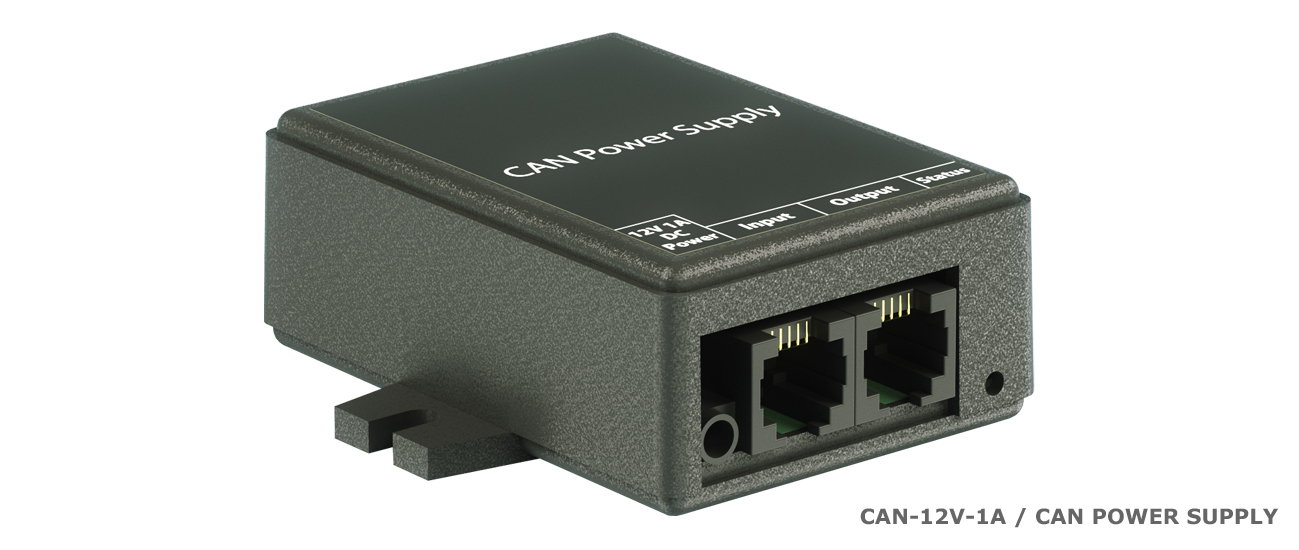
Function and purpose
Increases the number of CAN sensors connected on a CAN bus chain. Supplies power for a maximum of 15 additional sensors. Needed only if the number of sensors in a CAN bus chain is greater than 12 sensors.
Technical specifications
Communications | Description |
|---|---|
| Type | Power supply for CAN bus chain |
| Input | RJ11 6P4C CAN port ⌀3.4/1,35 mm 12V |
| Output | RJ11 6P4C CAN port |
| Daisy chain | Allows daisy chain |
| Max. q-ty of CAN sensors powered: | 15 |
| LED indicators: | Green (Status On/Off) |
| Environmental | |
| Working temperature range: | −40 °C до +100 °C |
| Humidity operating range: | 0-95% RH |
| Power Requirement | |
| Power input: | 12V DC, min. 1A, max.2A |
| Mechanics | |
| Dimensions: | 68 x 67 x 26,2 mm (LxWxH) |
| Packaging weight: | 190 g |
| Mounting options: | Desktop, Wall mount, Indoor |
| General | |
| Manufactured in: | Slovak Republic, European Union |
| Manufactured by: | Vutlan s.r.o. |
| HS code: | 8504 40 90 |
| Warranty: | 90 days |
Physical description
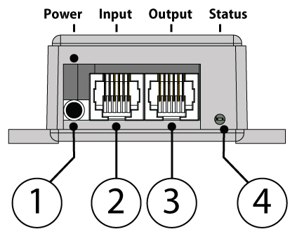
4. LED: "Status" (green) - indicates that the appliance is connected and operating.
2. "Power 12V DC" - power input.
3. "INPUT" - This port should be connected to a group of sensors towards the main monitoring unit.
4. "OUTPUT" - This port should be connected to a group of sensors further away from the monitoring unit.
Please, read carefully the instructions about connecting the unit. Connecting CAN sensors to the wrong CAN port on this device may burn the CAN bus line.
Drawings
Connecting the device
It is important that you read this article to the end before connecting the device. Connecting CAN sensors to the wrong CAN port on CAN-12V-1A may burn the CAN bus line.
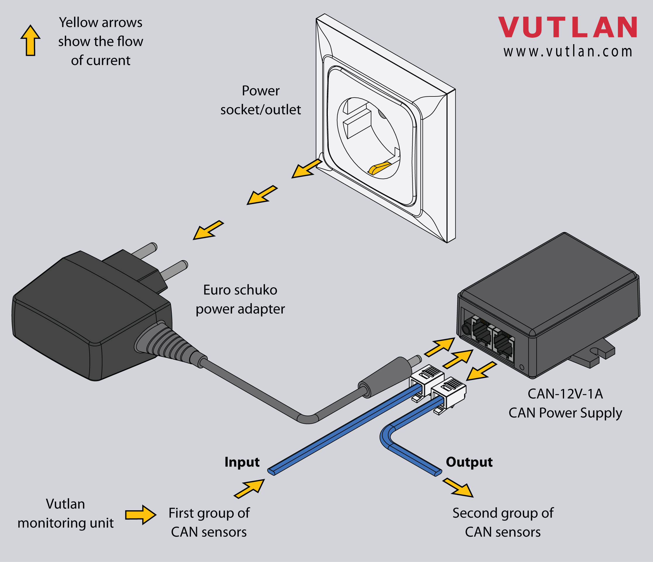
Description:
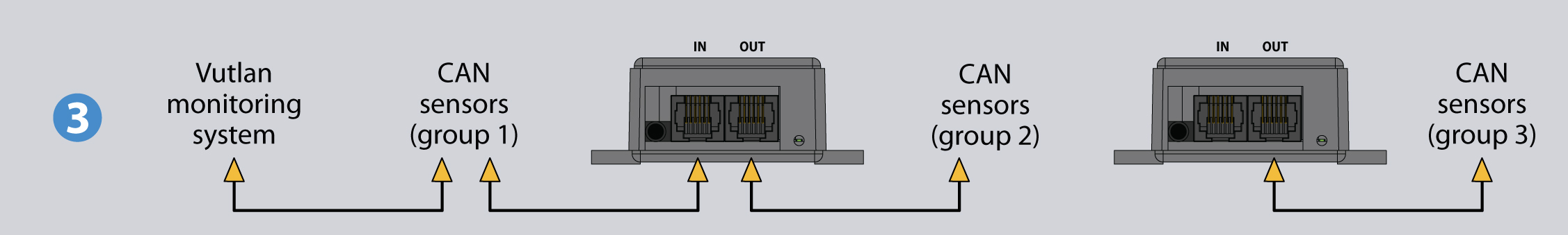
In our example, we have a monitoring system with a group of sensors (group 1) connected to it. CAN-12V-1A is only needed if we want to connect to the monitoring unit with more than 15 sensors.
Step 1:
- Plug CAN-12V-1A into the power supply socket using a Euro schuko power adapter. The status LED should light GREEN.
- Plug all additional sensors (group 2) into the "OUTPUT" port of CAN-12V-1A power supply unit. Group 2 should have no more than 15 sensors connected in a chain.
- All sensors should light ON. If some of the sensors do not switch ON, decrease the number of sensors connected to CAN-12V-1A, and check the status of each sensor again. If successful, continue to the next step.
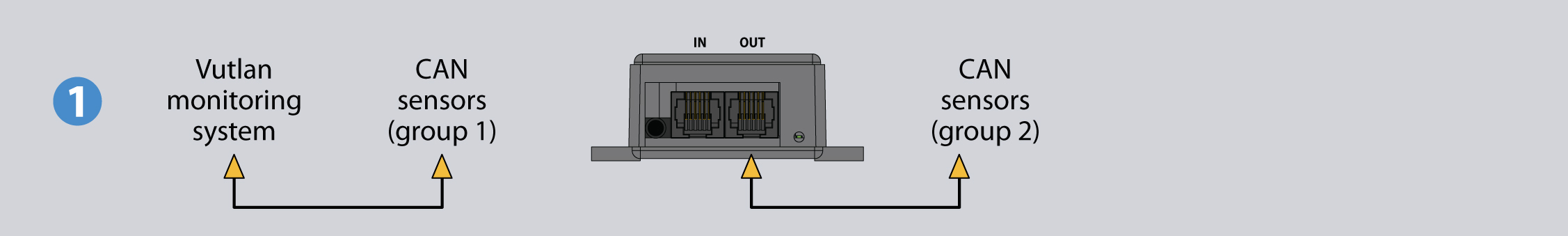
Step 2:
- Connect GROUP1's the last sensor to the INPUT port of CAN-12V-1A module.
- Switch the last sensors TR button to OFF position in GROUP1. Switch the last sensors TR button to ON position in GROUP2.
- You can now CONFIGURE the CAN bus in the web interface. See the "CAN Configuration" step below.
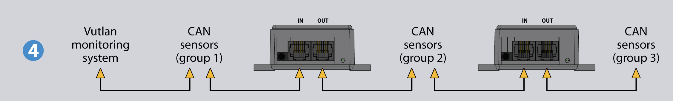
If you want to add more sensors, you will need to add an additional CAN-12V-1A module in a chain. The steps are identical for Step1 and Step2.
Connecting CAN devices
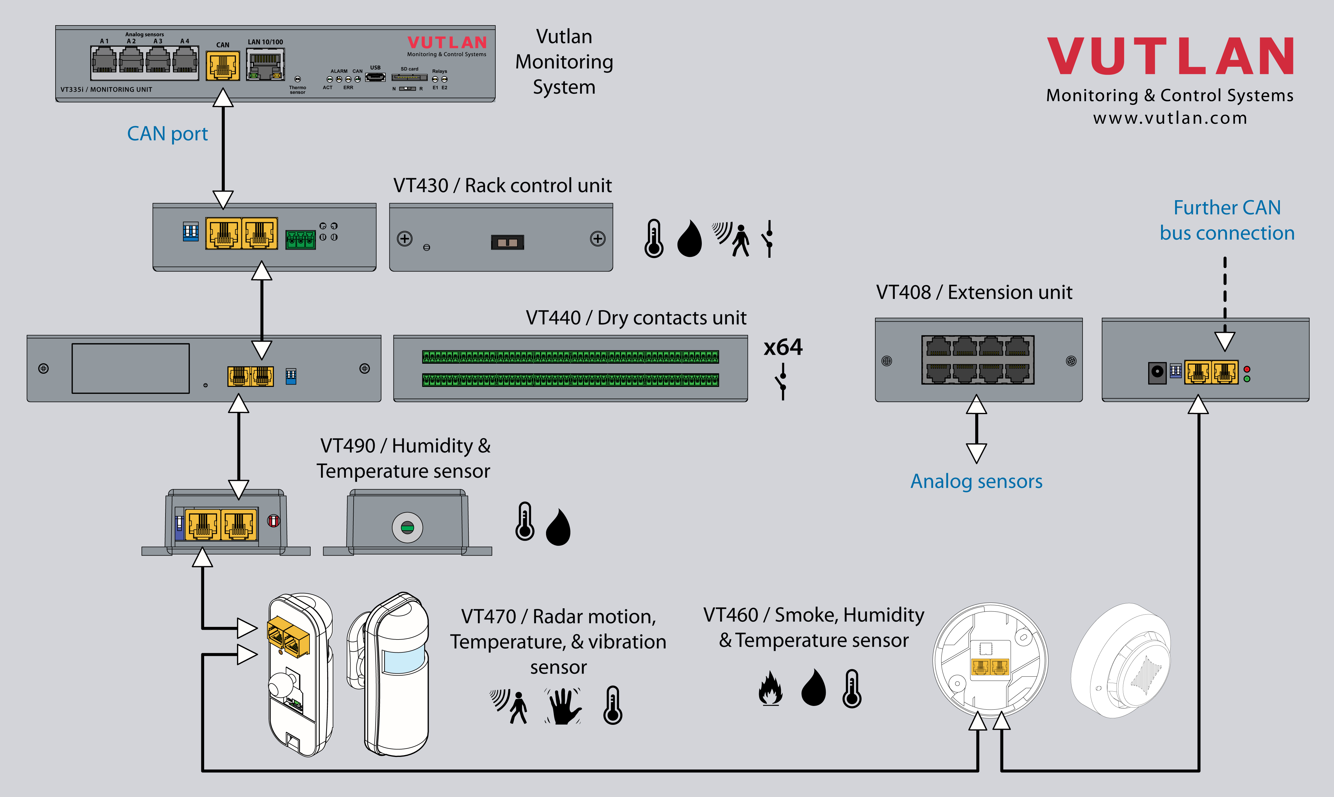
CAN sensors and CAN units connection
Connect CAN devices to any port CAN1 or CAN2 on the monitoring system using a cable supplied. CAN sensors can also be connected to the port of another CAN sensor or CAN unit that is connected to the CAN bus. Determination of the devices and their connection is done through a web interface.
You can connect up to a maximum of x12 CAN sensors and CAN devices together on one CAN bus (approximately)!
If you want to connect more than x12 CAN units, you need to use CAN-12V-1A / CAN Power Supply
You can connect up to x32 CAN units in a CAN bus chain.
The TR should be "ON" for the last sensor on each bus "CAN 1" and "CAN 2". See section "TR" below.
This procedure applies to the following sensors, which are supported by the appliance and are connected to the CAN ports:
CAN sensors, and modules:
CAN extensions:
Read more about Setting up CAN sensors.
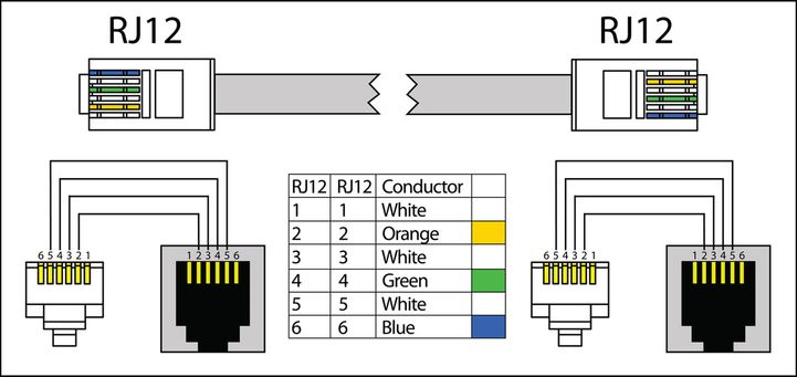
CAN cable and limited line length
The maximum length of the CAN line in Vutlan monitoring systems is 225 m due to limitations on the ohmic resistance of cables with RJ12 connectors.
Vutlan AWG24 cables have low resistance.
Since the conductivity of aluminum is much lower than that of copper, the resistance of CCA cables is much higher than that of pure copper cables of the same size.
It is advisable to use two or three pairs of cables such as UTP Cat3.5.6 with 24AWG with a copper core. It is possible to use a 4-wire or 6-wire TRONIC or UTP CCA cable, but the maximum CAN line length will be reduced.
TR termination switch
The last sensor TR switch on a CAN chain must always be terminated, ( switched ON ). Sensors on a CAN bus that is in the middle should have TR switched OFF.
FR should always be OFF.
TR switch is always the DP switch nearest to the CAN bus.
Only older Vutlan models have an FR switch.
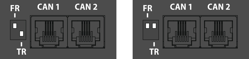
pic.1.1: FR is OFF, TR is ON. pic.1.2: FR is OFF, TR is OFF.
Adding CAN modules and sensors
To connect the CAN module or CAN sensor to the CAN bus of the system, go to the interface >> CAN configuration panel >> Select the CAN1 or CAN2 tab (select the connected physical CAN1 or CAN2 port on the master module).
Click the "Configure" button and wait. The system will start CAN bus polling, soon it will display the data lines and write “Done!”. The modules and sensors connected to the CAN input will appear in a tab in the list. Click the Apply button and then Restart.
The green LED "CAN status" of the device will light up.
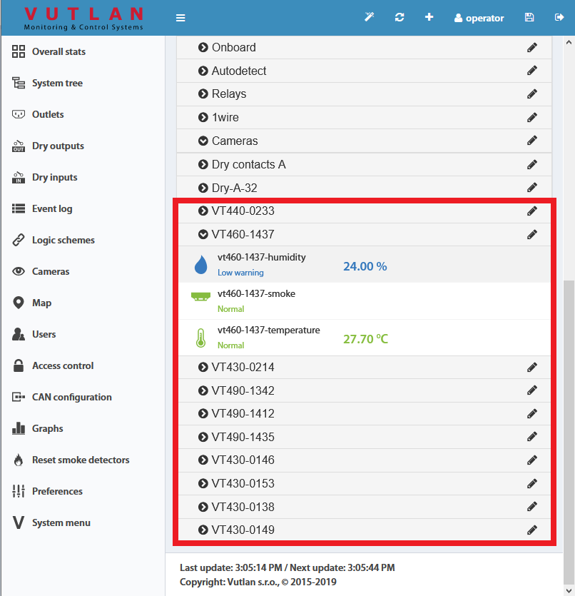
Go to the panel "System Tree" to see the new devices or new sensors. The article numbers for CAN devices are VT4xx. If they do not appear, wait, or refresh.
If after clicking the "Configure" button the poll is reset to the phrase "Update", then the line is not connected or the terminators on the bus are not agreed. It is necessary to check and change the condition of the TR terminators (See "TR termination switch" section above) on the modules or check and possibly change the connection cables.
Warning: If the bus is not matched, that is, there are bad contacts or bad cables, or the TR terminator is in the"ON" position on the intermediate devices (position 2 on the VT408), or the line is too short for matching on both CAN end devices, CAN on this line can work malfunctioning, or the line as a whole may not function. (CAN line failure may occur if the parallel CR switch is in state 1, must be in OFF).
LEDs
CAN sensors have LEDs that indicate the following states:
Red continuous light, green flickers - no communication with the master module
Red continuous light, green is off - there is a connection with the master unit but is not included in the monitoring system (not configured)
Red is off, Green continuously light - work as part of a monitoring system
All LEDs are off: no power or sensor is defective.
Maximum cable length test
Model | Description | 50m | 100m | 150m | 200m |
|---|---|---|---|---|---|
VT408 | Sensor extension unit | ok | |||
VT408DIN | ok | ||||
VT430 | Rack control unit | ok | |||
VT440 | Dry contacts unit | ok | long-chain | ||
VT460 | Smoke, humidity, temperature | ok | |||
VT490 / VT490i | Dual humidity and temperature sensor / Pressure, humidity & temperature sensor | ok |
Additional power for long-chain
When connecting a very long chain, you need to use the CAN-12V-1A / CAN Power Supply module for additional power for CAN units/extensions/sensors every 8-12 sensors.
x2 CAN port systems
Some Vutlan main monitoring systems have x2 CAN ports. That means they can support two individual CAN chains. Each chain has to be configured individually. E.g. “VT855t / Data center monitoring unit” has x2 CAN ports.
Additional reading
see also:
- Comparison chart: Extension units, CAN devices, Sensors
- VT408 / Analog sensor extension unit
- VT408DIN / Extension unit
- VT430 / Rack control unit
- VT440 / Dry contacts unit & VT32 / Dry contacts board extension
- VT450 / Pressure, humidity and temperature sensor
- VT490 / Humidity and temperature sensor
- CAN-12V-1A / CAN Power Supply
- VT460 / Smoke, humidity, temperature sensor (v8.1)
see also:
CAN configuration
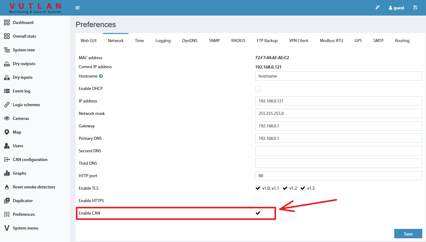
Enable CAN
Inside the web interface of the system go to >> Preferences menu >> Network tab >> Enable CAN >> Save >> Save settings to flash (An icon in the top right corner of the web interface)
Configuration
CAN bus is used for the connection of CAN sensors and CAN modules.
Before using the CAN sensor module, the CAN bus must be configured to operate with this CAN sensor module.
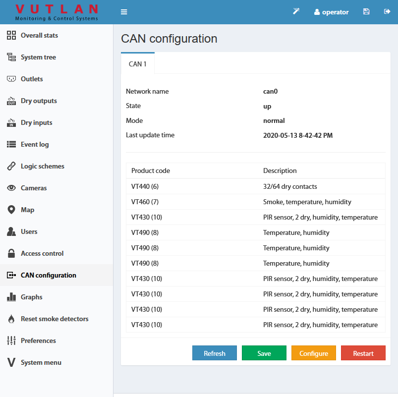
To configure the CAN bus go to "Main menu" >> "CAN configuration" menu.
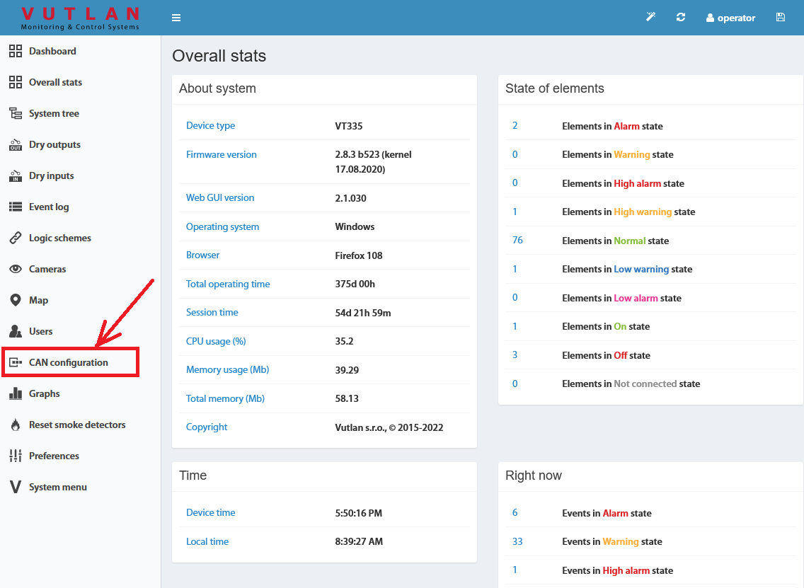
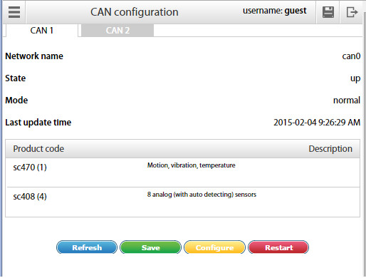
Each station tab contains current information on the status of the node and a list of CAN sensor modules connected to this node.
The following operations can be carried out on the CAN bus node:
Refresh - updates the current information on the status of the node;
Configure - launches configuration process of the nodes for CAN sensor modules connected to it, the old configuration is lost
Save - saves the list of CAN sensor modules in flash memory;
Restart - Restart the CAN bus node.
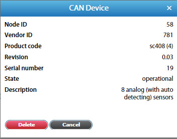
To delete a CAN sensor module, click on the desired module. A modal window will pop up. Press "Delete" and confirm.
To set up a CAN bus node for operation with the CAN sensor module, connect the CAN module to the CAN network and run the corresponding configuration procedure in the web interface using the command "Configure". The configuration process is displayed at the bottom of the tab and lasts approx. 2 minutes. Detected modules will be added to the list of modules during the configuration process. After completing configuration the node returns to its normal operation. Sensors of detected CAN modules are added to the tree of elements.
The names of the sensors are automatically set in the form {module name}{serial number}-{type of sensor} and can be edited.
If you need to remove the CAN sensor module from the configuration list use the command Delete, then use the command "Save" to apply the changes you made and restart the node using the command Restart.
Configuring VT408
The extension unit has built-in elements:
Power - relay type element
This element is identical to the element Analog Power of monitoring units. It turns on or off the power of analog sensors. Turning off the power of analog sensors for a few seconds is used to reset the alarm smoke detectors VT560 connected to the extension unit VT408.
Warning: when the power of analog sensors is OFF, all connected to the VT408 external sensors are OFF.
The settings of analog sensors connected to the VT408 unit are similar to the settings of sensors connected to the monitoring unit.
Additional reading
Packaging includes
Make sure that the contents of the delivery meet the following configuration. Report a missing or damaged component to your supplier. If damage occurred during transportation, contact the appropriate delivery service.
Package content | Description | Quantity | |
|---|---|---|---|
1 | 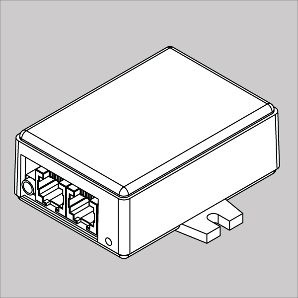 | CAN Power supply module | 1 pc |
2 | 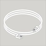 | RJ11 6P4C 2m CAN cable | 1 pc |
3 | 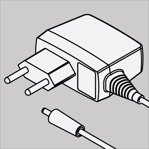 | 12V DC power supply | 1 pc |
4 | 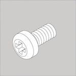 | Screws M3.5 10mm | 2 pcs |
5 | 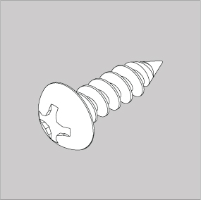 | Screws B3,5 13,5mm | 2 pcs |
6 |  | Nuts M3.5 | 2 pcs |
7 |  | M3.5 washers | 2 pcs |
8 |  | Self-adhesive sticker | 2 pcs |
Copyright:
Vutlan s.r.o.
Remote Infrastructure Monitoring and Control
43 ul.Svornosti, 821 06 Bratislava,
Slovak Republic, E.U.