Connection diagram
Monitoring units VT335 has the possibility to install VT700 / GSM modem. The device is mounted and connected inside of master monitoring unit. Needed when network is absent or for reservation of a connection channel of master unit with Internet; for sending SMS notifications and SMS commands.
Supply includes
| № | Component | Description |
|---|---|---|
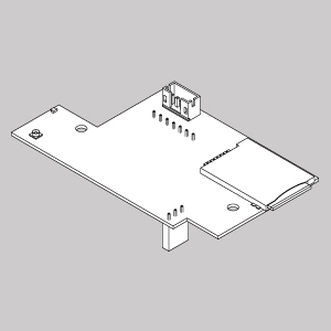
| 1 |
| VT700 / GSM modem board |
| 2 | Antenna | |
| 3 | Antenna wire | |
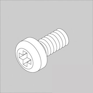
| 4 |
| M3*5mm bolts. 2pcs |
...
| Note |
|---|
To install and to connect extension units: switch off appliance, unplug from the outlet or disconnect the power connector. |
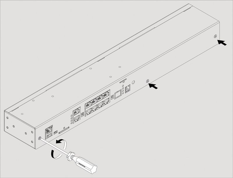
| 1 | Carefully unscrew three screws holding the cover and open it.
| |||
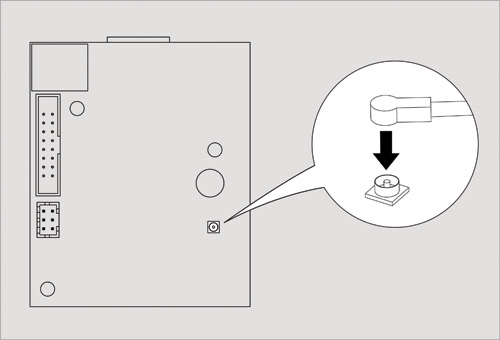
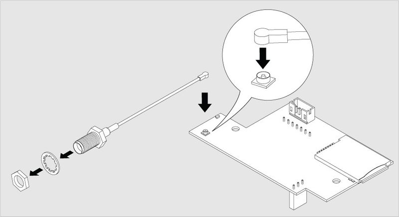
| 2 | 1) Connect antenna cable to the modem board. Carefully connect the U-Fl antenna cable to the input U-FL connector and gently press it. If possible install the connector on the seat with a magnifying glass! 2) Unscrew the nut and washer from antenna cable | |||
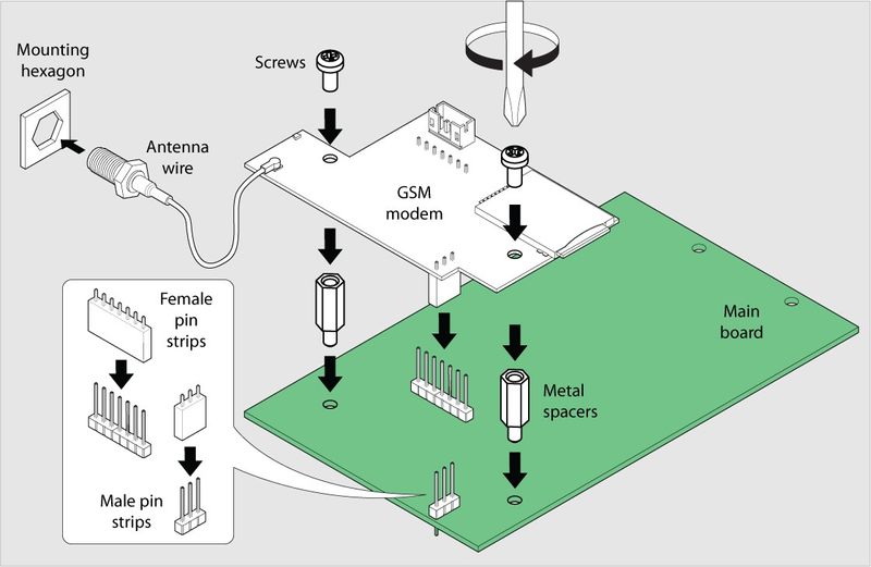
| 3 | Set up the GSM modem card on 3 steel spacing sleeves on the cover, attach card to the sleeves using three M3 screws supplied with the modem. | |||
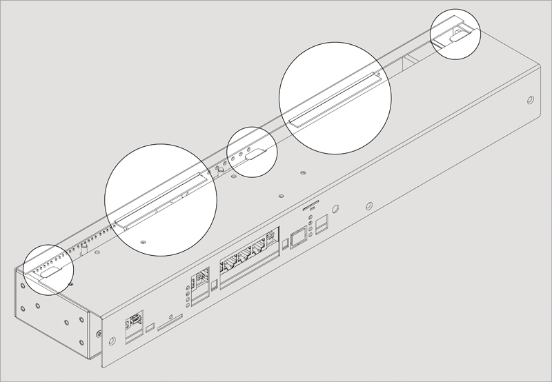
| 4 | Set the SMA connector antenna cable to the rear or to the front panel of the appliance into the corresponding SMA hole. Put on the SMA connector gold-plated washer and nut from the supply, holding SMA connector with one key, securely tighten the nut with the other key.
| |||
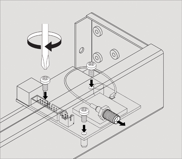
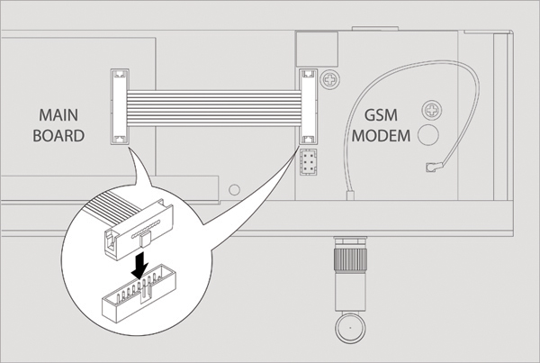
| 5 | Connect 16-pin flat cable to the connectors on the modem card and on the appliance motherboard. Close and fasten the cover. If necessary, install the SIM card into the appropriate hole | 1) Main board should already have two metal spacers mounted on it. If it does not, please request them from the manufacturer. 2) Place GSM modem above the metal spacers and male pin strips located on the main board. Gently push the GSM board downwards so that: a) Male pin strip on main board(3pins) inserts into Female pin socket on GSM board (3pincs) b) Male pin strip on main board(7pins) inserts into Female pin socket on GSM board (7pincs) c) Two holes on GSM board are located directly above metal spacers and the GSM board touches metal spacers. 3) Screw two M3 screws supplied with the modem through the holes into metal spacers as shown on the picture. 4) Insert antenna wire into hexagon mounting hole located at the front or at the back of the unit (e.g. VT335 has a front hole SMA only) | ||
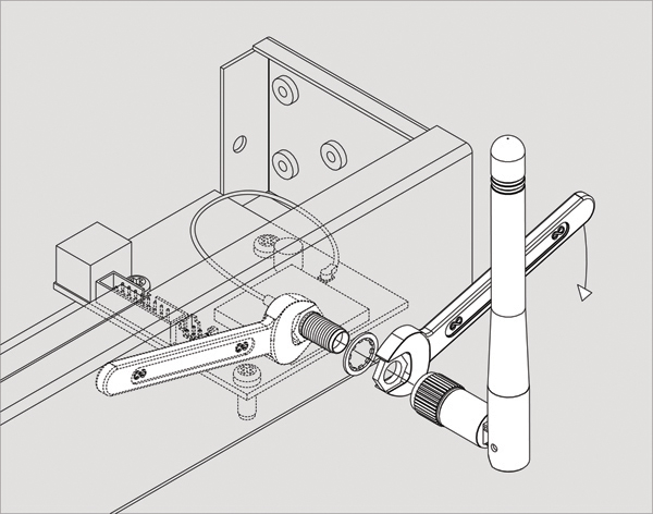
| 4 | 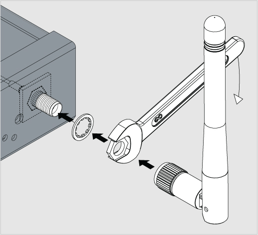 | The antenna wire should now stick out to the front or to the rear of the unit (e.g. VT335 has a front hole) just like shown on the picture. 1. Put a washer on the end of the antenna wire thread. 2. Screw the nut on to the antenna wire thread to the maximum with your hands. 3. Now use a wrench to tighten the nut
4. Screw the antenna to the end of antenna wire thread. | ||
| 6 | Carefully place top cover back so that all cover wings fit in and all cutoffpoints match the panel holes. Then use 3 screws to close the enclosure. When installing the green dry contact connectors can go tight, check the burrs and remove them with rasp! |